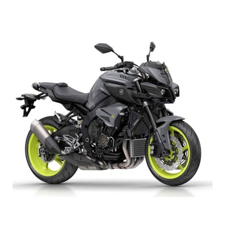


YAMAHA MTN1000 (MT10) - SERVICE MANUAL - WIRING DIAGRAMS
- English Service Manual / Repair Manual and Wiring Diagrams, for Yamaha MTN1000 MT10 from 2016.
CONTENTS:
GENERAL INFORMATION
- Identification
- Features
- Important Information
- Basic Service Information
- Special Tools
SPECIFICATIONS
- General Specifications
- Engine Specifications
- Chassis Specifications
- Electrical Specifications
- Tightening Torques
- Lubrication Points And Lubricant Types
- Lubrication System Chart And Diagrams
- Cooling System Diagrams
- Cable Routing
PERIODIC CHECKS AND ADJUSTMENTS
- Periodic Maintenance
CHASSIS
- General Chassis (1)
- General Chassis (2)
- General Chassis (3)
- Front Wheel
- Rear Wheel
- Front Brake
- Rear Brake
- Abs (Anti-Lock Brake System)
- Handlebar
- Front Fork
- Steering Head
- Rear Shock Absorber Assembly
- Swingarm
- Chain Drive
ENGINE
- Engine Inspection
- Engine Removal
- Camshafts
- Cylinder Head
- Valves And Valve Springs
- Generator
- Starter Clutch
- Electric Starter
- Oil Pump
- Clutch
- Shift Shaft
- Crankcase
- Connecting Rods And Pistons
- Crankshaft And Balancer Shaft
- Transmission
COOLING SYSTEM
- Radiator
- Oil Cooler
- Thermostat
- Water Pump
FUEL SYSTEM
- Fuel Tank
- Throttle Bodies
- Air Induction System
ELECTRICAL SYSTEM
- Ignition System
- Electric Starting System
- Charging System
- Lighting System
- Signaling System
- Cooling System
- Fuel Injection System
- Cruise Control System
- Fuel Pump System
- Immobilizer System
- Abs (Anti-Lock Brake System)
- Steering Damper System
- Electrical Components
TROUBLESHOOTING
- Troubleshooting
- Self-Diagnostic Function And Diagnostic Code Table
- Event Code Table
WIRING DIAGRAM
