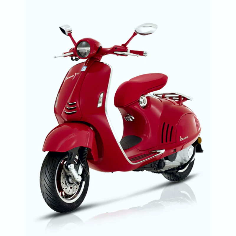
VESPA 946 - WORKSHOP, SERVICE, REPAIR MANUAL - WIRING DIAGRAMS - OWNERS MANUAL
- English Service Manual / Repair Manual, Owners Manual and Wiring Diagrams, for motorcycles Vespa 946.
CONTENTS:
SERVICE MANUAL
-Vespa 946
- Characteristics
- Rules
- Safety rules
- Maintenance rules
- Vehicle identification
- Dimensions and mass
- Engine
- Transmission
- Capacities
- Electrical system
- Frame and suspensions
- Brakes
- Wheels and tyres
- Tightening Torques
- Overhaul data
- Assembly clearances
- Cylinder - piston assy.
- Crankcase - crankshaft - connecting rod
- Cylinder Head
- Slot packing system
- Products
- Tooling
- Maintenance
- Maintenance chart
- Spark plug
- Hub oil
- Check
- Replacement
- Air filter
- Engine oil
- Replacement
- Check
- Engine oil filter
- Oil pressure warning light
- Checking the ignition timing
- Checking the valve clearance
- Braking system
- Level check
- Top-up
- Headlight adjustment
- Troubleshooting
- Engine
- Poor performance
- Starting difficulties
- Excessive oil consumption/Exhaust smoke
- Insufficient lubrication pressure
- Transmission and brakes
- Clutch grabbing or performing inadequately
- Insufficient braking
- Brakes overheating
- Electrical system
- Battery
- Steering and suspensions
- Heavy steering
- Excessive steering play
- Noisy suspension
- Suspension oil leakage
- Electrical system
- Components arrangement
- Ground points
- Electrical system installation
- Front side
- Back side
- Conceptual diagrams
- Ignition
- Battery recharge and starting
- Level indicators and enable signals section
- Devices and accessories
- Lights and turn indicators
- Checks and inspections
- Immobiliser
- Virgin circuit
- Diagnostic codes
- Diagnostic code - 1 flash
- Diagnostic code - 2 flashes
- Diagnostic code - 3 flashes
- Battery recharge circuit
- Stator check
- Recharge system voltage check
- Starter motor
- Horn control
- Turn signals system check
- level indicators
- Lights list
- Fuses
- Dashboard
- Sealed battery
- Battery installation
- Connectors
- Diagnostic instrument
- Engine from vehicle
- Exhaust assy. Removal
- Removal of the engine from the vehicle
- Engine
- Automatic transmission
- Transmission cover
- Air duct
- Removing the driven pulley shaft bearing
- Refitting the driven pulley shaft bearing
- Removing the driven pulley
- Inspecting the clutch drum
- Removing the clutch
- Inspecting the clutch
- Pin retaining collar
- Removing the driven half-pulley bearing
- Inspecting the driven fixed half-pulley
- Refitting the driven half-pulley bearing
- Refitting the driven pulley
- Inspecting the clutch spring
- Refitting the driven pulley
- Drive-belt
- Removing the driving pulley
- Inspecting the rollers case
- Refitting the driving pulley
- Refitting the transmission cover
- End gear
- Removing the hub cover
- Removing the hub bearings
- Removing the wheel axle bearings
- Inspecting the hub shaft
- Inspecting the hub cover
- Refitting the driven pulley shaft bearing
- Refitting the hub cover bearings
- Refitting the ub cover
- Flywheel cover
- Cooling hood
- Cooling fan
- Removing the hub cover
- Removing the stator
- Refitting the stator
- Refitting the flywheel cover
- Flywheel and starting
- Removing the starter motor
- Removing the flywheel magneto
- Inspecting the flywheel components
- Refitting the flywheel magneto
- Refitting the starter motor
- Cylinder assy. and timing system
- Removing the intake manifold
- Removing the rocker-arms cover
- Removing the timing system drive
- Removing the cam shaft
- Removing the cylinder head
- Removing the valves
- Removing the cylinder - piston assy.
- Inspecting the small end
- Inspecting the wrist pin
- Inspecting the piston
- Inspecting the piston rings
- Removing the piston
- Choosing the gasket
- Refitting the piston rings
- Refitting the cylinder
- Inspecting the cylinder head
- Inspecting the timing system components
- Inspecting the valve sealings
- Inspecting the valves
- Inspecting the springs and half-cones
- Refitting the valves
- Inspecting the cam shaft
- Refitting the head and timing system components
- Refitting the rocker-arms cover
- Refitting the intake manifold
- Crankcase - crankshaft
- Splitting the crankcase halves
- Inspecting the crankshaft components
- Inspecting the crankshaft alignment
- Inspecting the crankcase halves
- Inspecting the crankshaft plain bearings
- Coupling chart
- Refitting the crankcase halves
- Studs
- Lubrication
- Conceptual diagrams
- Oil pressure check
- Crankshaft oil seals
- Removal
- Refitting
- Oil pump
- Removal
- Inspection
- Refitting
- Removing the oil sump
- Inspecting the by-pass valve
- Refitting the oil sump
- Injection
- Precautions
- Terminals setup
- EMS circuit diagram
- Troubleshooting procedure
- Engine does not start
- Starting difficulties
- Engine stops at idle
- Engine does not rev down
- Exhaust backfires in deceleration
- Engine revs irregularly
- Poor performance at full throttle
- Engine knocking
- Fuel supply system
- Refitting the injector
- Removing the butterfly valve
- Refitting the butterfly valve
- Pump supply circuit
- Fuel filter check
- Inspecting the injector circuit
- Inspecting the injector hydraulics
- Tachometer
- Suspensions
- Front
- Removing the front wheel
- Front wheel hub overhaul
- Refitting the front wheel
- Handlebar
- Removal
- Refitting
- Steering column
- Removal
- Overhaul
- Refitting
- Front shock absorber
- Removal
- Refitting
- Shock-absorber - calliper bracket
- Removal
- Overhaul
- Refitting
- Rear
- Removing the rear wheel
- Refitting the rear wheel
- Swing-arm
- Removal
- Overhaul
- Refitting
- Shock absorbers
- Removal
- Refitting
- Centre-stand
- Braking system
- ABS
- Operating diagram
- Guide to diagnosis
- Modulator
- ASR
- System ASR
- Rear brake calliper
- Removal
- Refitting
- Front brake calliper
- Removal
- Refitting
- Rear brake disc
- Removal
- Refitting
- Disc Inspection
- Front brake disc
- Removal
- Refitting
- Disc Inspection
- Front brake pads
- Removal
- Refitting
- Rear brake pads
- Removal
- Refitting
- Fill
- Rear - combined
- Front
- Brake fluid level check
- Front brake pump
- Removal
- Refitting
- Rear brake pump - combined
- Removal
- Refitting
- Brake pipes
- Chassis
- Seat
- Side fairings
- Driving mirrors
- Rear handlebar cover
- Instrument panel
- Front handlebar cover
- Headlight assy.
- Legshield
- Knee-guard
- Removing the ignition key-switch when on *off*
- Removing the ignition key-switch when on *lock*
- Taillight assy.
- License plate light
- Footrest
- Side fairings
- License plate holder
- Air filter
- Rear mudguard
- Vano portabatterie - inverter
- spoiler
- Fuel tank
- Front mudguard
- Pre-delivery
- Aesthetic inspection
- Tightening torques inspection
- Electrical system
- Levels check
- Road test
- Static test
- Functional inspection
- Specific operations for the vehicle
PARTS CATALOGUE
-Index
-Finished products
-Alphanumeric index
-Engine
- Table 01.02 - Engine, assembly
- Table 01.05 - Crankcase
- Table 01.06 - Crankshaft
- Table 01.07 - Cylinder-piston-wrist pin unit
- Table 01.10 - Head unit - Valve
- Table 01.11 - Rocking levers support unit
- Table 01.12 - Cylinder head cover
- Table 01.13 - Driving pulley
- Table 01.14 - Driven pulley
- Table 01.15 - Crankcase cover - Crankcase cooling
- Table 01.18 - Oil pump
- Table 01.20 - Stater - Electric starter
- Table 01.21 - Flywheel magneto
- Table 01.23 - Flywheel magneto cover - Oil filter
- Table 01.25 - Reduction unit
- Table 01.36 - Throttle body - Injector - Union pipe
- Table 01.42 - Silencer
- Table 01.45 - Air filter
-Frame - Plastic parts - Coachwork
- Table 02.01 - Frame/bodywork
- Table 02.25 - Stand/s
- Table 02.26 - Front shield
- Table 02.30 - Front glove-box - Knee-guard panel
- Table 02.31 - Central cover - Footrests
- Table 02.32 - Side cover - Spoiler
- Table 02.33 - Wheel huosing - Mudguard
- Table 02.37 - Rear cover - Splash guard
- Table 02.38 - Plates - Emblems
- Table 02.39 - Saddle/seats - Tool roll
- Table 02.45 - Driving mirror/s
- Table 02.46 - Locks
- Table 02.47 - Fuel tank
-Handlebars/Steering
- Table 03.01 - Handlebars coverages
- Table 03.02 - Meter combination - Cruscotto
- Table 03.06 - Handlebars - Master cil.
-Suspensions - Wheels
- Table 04.01 - Swinging arm
- Table 04.02 - Fork/steering tube - Steering bearing unit
- Table 04.10 - Rear suspension - Shock absorber/s
- Table 04.11 - Front wheel
- Table 04.12 - Rear wheel
-Braking system - Transmissions
- Table 05.02 - Brakes pipes - Calipers (ABS)
- Table 05.03 - Transmissions
-Electrical system
- Table 06.01 - Selectors - Switches - Buttons
- Table 06.03 - Front headlamps - Turn signal lamps
- Table 06.04 - Rear headlamps - Turn signal lamps
- Table 06.05 - Remote control switches - Battery - Horn
- Table 06.06 - Voltage Regulators - Electronic Control Units (ecu) - H.T. Coil
- Table 06.08 - Main cable harness
WIRING DIAGRAM
OWNERS MANUAL