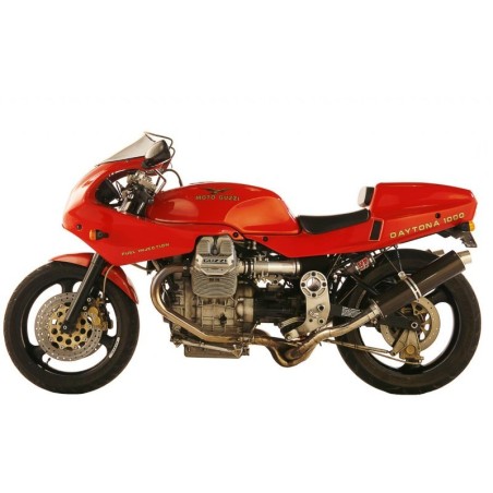


MOTO GUZZI DAYTONA 1000 - MANUALE DI OFFICINA - WORKSHOP MANUAL - PARTS
- Multilanguage (English, Italiano) Service Manual and Spare Parts Catalogue, to Moto Guzzi Daytona 1000.
CONTENTS:
IDENTIFICATION DATA
- 1.1 Spare Parts 6
GENERAL FEATURES
INSTRUMENTS AND CONTROLS
- 3.1 Control panel 11
- 3.2 Light switches 12
- 3.2.1 Switch, hazard warning lights 12
- 3.3 Horn Button, Headlamp Flasher and direction indicators 12
- 3.4 «Choke» control 12
- 3.5 Clutch lever 13
- 3.6 Starter Button and Engine Stop Switch 13
- 3.7 Throttle twist grip 13
- 3.8 Brake lever, front brake 13
- 3.9 Brake pedal for rear brake 13
- 3.10 Gearbox control pedal 13
- 3.11 Fuel filler cap 14
- 3.12 Fuel tap 14
- 3.13 Electric fuel cock 14
- 3.14 Fuse box 15
- 3.15 Steering damper 15
- 3.16 Documents and objects holder 16
- 3.17 Helmet holder 16
- 3.18 Motorbike lateral supporting arm 16
- 3.18.1 Side stand for motorcycle support with safety switch 17
- 3.19 Driver seat removal 17
- 3.20 removing the saddle 17
- 3.21 Passenger holding belt 18
LUBRICATION
- 4.1 Engine lubrication 19
- 4.2 changing the filter cartridge and cleaning the mesh filter 19
- 4.3 Gearbox lubrication 20
- 4.4 Rear transmission box lubrication 20
- 4.5 greasing the driving shaft 21
- 4.6 Front fork oil change 21
- 4.7 Greasing 21
MAINTENANCE AND ADJUSTMENTS
- 5.1 adjusting the clutch lever 22
- 5.2 adjusting the front brake lever 22
- 5.3 Rear brake pedal adjustment 23
- 5.4 adjusting the steering 23
- 5.5 Adjustment of telescopic fork. 24
- 5.6 Rear suspension adjustment 24
- 5.7 changing the air filter 26
- 5.7.1 Changing the air filter 27
- 5.8 Tappet clearance checking 28
- 5.8.1 Timing belts 28
- 5.9 adjusting the headlight beam 28
- 5.10 cleaning the windscreen 29
- 5.11 motor washing rules 29
SERVICE SCHEDULE
ENGINE UNIT
- 10.1 dismantling the engine assembly 42
- 10.1.1 Engine reassembly 50
- 10.1.2 Timing system phase-setting check 54
- 10.2 Checks 55
- 11.1 Engine dismantling
- 11.2 Engine reassembly 78
- 11.3 Engine timing 82
- 11.4 Checks 87
WEBER INJECTION IGNITION UNIT
- 12.1 System components 102
- 12.2 Operation phases 1
- 12.3 Fuel circuit 05
- 12.4 Air circuit 1
- 12.5 Electric circuit 107
- 12.6 Calibration rules for carburation and regulation of the engine 111
- 12.7 Trimmer operation on the electronic control unit type I AW 16M for C- regulation 112
- 12.8 Starter lever adjustment 113
- 12.9 Adjustment of the starter RPM 113
- 12.10 Induction system control 113
- 12.11 Use of the check lamp for the defects detection 1
- 12.12 Reset procedure for the electronic control unit I AW 16M 11
- 12.13 Sparkplugs 11
- 12.14 Evaporative emission control system 119
CLUTCH
GEARBOX
- 14.1 Gearbox lubrication 124
- 14.2 Disassembly 124
- 14.3 Reassembly 129
REAR DRIVE
- 15.1 Rear drive box lubrication 132
- 15.2 Drive box disassembly 132
- 15.3 Reassembly 134
- 15.4 Transmission shaft 136
FRAME
FRONT FORK
- 17.1 Change the fork oil 142
- 17.2 Disassemble fork stem 142
- 17.3 Removal of the screwed cap 142
- 17.4 Oil draining 144
- 17.5 Cartridge disassembly 144
- 17.6 Oil refilling 145
- 17.7 substituting the oil retainer bushing 146
REAR SUSPENSION
WHEELS
- 19.1 Front wheel 152
- 19.2 Rear wheel 153
- 19.3 Tires 154
BRAKE SYSTEM
- 20.1 Checking brake pads wear 157
- 20.2 checking the brake fluid in the master cylinder reservoir 157
- 20.3 checking brake disks 158
- 20.4 Air bleeding from braking circuit 161
ELECTRICAL EQUIPMENT
- 21.1 Battery 163
- 21.2 Alternator and voltage controller 164
- 21.3 Starter motor 166
- 21.4 lighting equipment 167
- 21.4.1 Replacing bulbs 167
- 21.5 Key t- wiring diagram 170
PARTS MANUAL