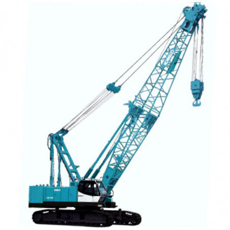

KOBELCO CK1200 & CKE1100 - WORKSHOP, SERVICE, REPAIR MANUAL - WIRING DIAGRAMS
- English Service Manual and Wiring Diagrams, for Crawler Crane Kobelco CK1200 CKE1100.
CONTENTS:
1. SPECIFICATION
-1.1 Specification
- 1.1.1 Performance
- 1.1.2 Outside Dimensions
- 1.1.3 Dimensions And Weight Of Each Parts
- 1.1.4 Stability In Swinging And Traveling
2. MAINTENANCE STANDARDS TEST PROCEDURES
-2.1 Maintenance Standard
- 2.1.1 Pin, Bushing, Spring, Lining And Sheave
- 2.1.2 Propel Device
- 2.1.3 Propel Brake Plate
-2.2 Performance Standard And Test Procedure
- 2.2.1 Operating Speed
- 2.2.2 Point And Method Of Measuring Pressure
- 2.2.3 Slewing Ring
3. GENERAL WORK STANDARD
-3.1 Tightening Torque Of Capscrews And Nuts
- 3.1.1 Metric Coarse Threads
- 3.1.2 Metric Fine Threads
- 3.1.3 Coarse Threds Unc
- 3.1.4 Fine Threads Unf
- 3.1.5 Tightening Torque Of Hydraulic Fittings
-3.2 Standard Parts
- 3.2.1 Bolt
- 3.2.2 O-Ring
- 3.2.3 Back-Up Ring
- 3.2.4 Bite Fitting
-3.3 Conversion Table
- 3.3.1 Unit Conversion
- 3.3.2 Millimeter : Inch Conversion Table
- 3.3.3 Meter-Foot Conversion Table
- 3.3.4 Gradient Conversion Table
-3.4 Table Of Unit Weight
4. POWER TRAIN
-4.1 Introduction
-4.2 Engine
- 4.2.1 Introduction
- 4.2.2 Removal
- 4.2.3 Repair And Maintenance
- 4.2.4 Re-Installation
-4.3 Pump Drive Assembly
- 4.3.1 Introduction
- 4.3.2 Removal
- 4.3.3 Disassembling The Power Divider
- 4.3.4 Check And Repair Of The Power Divider
- 4.3.5 Assembling The Power Divider
- 4.3.6 Re-Installation
5. HYDRAULIC SYSTEM
-5.1 Location Of Main Hydraulic Components
-5.2 Hydraulic Circuits And Components
- 5.2.1 Hydraulic Circuit
- 5.2.2 Component Specifications
- 5.2.3 Location Of Hydraulic Components
-5.3 Hydraulic System
- 5.3.1 Preface
- 5.3.2 Outline
- 5.3.3 Oil Flow From No.1 And No. 2 Pumps
- 5.3.4 Oil Flow From No.3 And No.4 Pumps
- 5.3.5 Oil Flow From No.5 Pumps (Control Pumps)
- 5.3.6 Oil Flow From No.6 Pump (For Auxiliary Actuator Circuit)
-5.4 Valves
6. HOIST SYSTEM
-6.1 Apparatus And Location Of Components
-6.2 Construction And Function
- 6.2.1 Hydraulic Schematic
- 6.2.2 Lifting A Load
- 6.2.3 Holding A Raised Load
- 6.2.4 Lowering A Load (Powered Lowering)
- 6.2.5 Free Fall Operation
- 6.2.6 Free Fall Acceleration
-6.3 Drum Lock
- 6.3.1 Aseembly Drawing
- 6.3.2 Adjustment Of Drum Lock
-6.4 Winch Assembly
- 6.4.1 Winch Instal
- 6.4.2 Winch Assembly / Reduction Unit Without Free Fall (Std.)
- 6.4.3 Winch Assembly With Free Fall (Opt.)
-6.5 Brake Pedal
- 6.5.1 Assembly Drawing
- 6.5.2 Adjusting The Brake Pedal
-6.6 Bleeding Air From Brake Circuit
7. BOOM HOIST SYSTEM
-7.1 Apparatus And Location Of Components
-7.2 Construction And Function
- 7.2.1 Hydraulic Schematic
- 7.2.2 Raising The Boom
- 7.2.3 Neutral
- 7.2.4 Lowering The Boom
-7.3 Boom Drum Lock
- 7.3.1 Assembly Drawing
- 7.3.2 Adjusting The Boom Drum Lock
-7.4 Drum And Reduction Unit
- 7.4.1 Boom Winch Assembly
- 7.4.2 Boom Drum And Reduction Unit Assembly
8. SWING SYSTEM
-8.1 Apparatus And Location Of Components
-8.2 Construction And Function
- 8.2.1 Hydraulic Schematic
- 8.2.2 Swing
- 8.2.3 Stopping
-8.3 Swing Reduction Unit
-8.4 Swing Bearing
-8.5 Swing Lock
9. PROPEL SYSTEM
-9.1 Location Of The Major Components
-9.2 Construction And Function
- 9.2.1 Hydraulic Schematic
- 9.2.2 Propelling (Right Side Forward)
- 9.2.3 Stopping
-9.3 Propel Reduction Unit
- 9.3.1 Motor And Reduction Unit
-9.4 Adjustment
10. ELECTRIC SYSTEM
-10.1 Electrical Wiring Schematic
-10.2 Connector List
-10.3 Arrangement Of Electrical Part
- 10.3.1 Electrical Part Of Cab
- 10.3.2 Electrical Part Of Right Deck
- 10.3.3 Electrical Part Of Floor Plate & Left Side Stand Panel
- 10.3.4 Electrical Part Of Revolving Frame
- 10.3.5 Electrical Part Of Left Deck
- 10.3.6 Electrical Part Of Left Guard
-10.4 Electrical Part
- 10.4.1 Fuse Box (Gg73e00004f1)
- 10.4.2 Wiper Control Unit (2480u306)
- 10.4.3 Swing Flasher Unit (2480u306)
- 10.4.4 Pressure Switch (Control Pressure Cut & Free Fall) (Gg52s00006p1)
- 10.4.5 Pressure Sensor
- 10.4.6 Relay Box (Gg24e00024f1)
- 10.4.7 Left Side Stand Panel
-10.5 Troubleshooting Of Exhaust Gas Third Regulation Engine
- 10.5.1 Failure Diagnosis Function
- 10.5.2 How To Check The Failure Contents
- 10.5.3 Checking Blown-Off Diagnosis Lamps
- 10.5.4 Engine Ecu
11. LOAD SAFETY DEVICE
-11.1 Part Names And Functions
- 11.1.1 Front View
- 11.1.2 Configuration Of Screens
- 11.1.3 Data Transmission Between Controller And Cards
- 11.1.4 Details Of Indicators On Main Display Screen
- 11.1.5 Rear View
- 11.1.6 Items Required To Be Executed For Replacement Of Controller Or Data Card And Instructions
-11.2 Preparation For Use
-11.3 Turn The Power On
-11.4 Upgrading Programs
- 11.4.1 Procedures
- 11.4.2 Upgrading Of Indication Programs
- 11.4.3 Upgrading Of Control Programs
-11.5 Status Check
- 11.5.1 Signal Check
- 11.5.2 Operation Progress
- 11.5.3 Communication Data
- 11.5.4 Indication Of Adjustment Value
- 11.5.5 Load Record
- 11.5.6 Trouble Record
- 11.5.7 Choice Of Language (Cke Series Only)
- 11.5.8 Load Record (Load Record In The Main Menu)
-11.6 Adjustments
- 11.6.1 Removing The Inner Panel
- 11.6.2 Adjustment
- 11.6.3 Load Adjustment
- 11.6.4 Adjustment Data Copy (Initialization)
- 11.6.5 Version Check
-11.7 Error Code (Abnormality Detection) And Countermeasures
-11.8 Control Output
-11.9 Releases
- 11.9.1 Release Function
-11.10 Mechanical Specification
- 11.10.1 Environmental Performance Parameters
- 11.10.2 Load Cell (Crane)
- 11.10.3 Angle Sensor
- 11.10.4 Controller
-11.11 External Dimensions
-11.12 Electric Schematic Diagram
- 11.12.1 Crane Type
- 11.12.2 Luffing Type
-11.13 Controller Malfunction Emergency Measures
-11.14 Load Safety Device Check Procedures
12. GAUGE CLUSTER
-12.1 Configuration Of Display
-12.2 Priority
-12.3 Status Display
-12.4 Fault Log Display
13. TOTAL CONTROLLER
-13.1 Arrangement Of Total Controller
-13.2 Composition Of System
- 13.2.1 Output Relation To Controller
-13.3 Function Of Total Controller
-13.4 Total Controller (Hardware)
- 13.4.1 Outline
- 13.4.2 Specifications Of Total Controller Output
- 13.4.3 Details Of Total Controller Connector
- 13.4.4 Arrangement Of Total Controller Connector Pin
- 13.4.5 Proportional Solenoid Valve Measuring Position
-13.5 Adjustment Of Total Controller
- 13.5.1 Necessity Of Adjustment
- 13.5.2 Adjustment Procedures Of Total Controller
14. AIR CONDITIONER
-14.1 Operation Items
-14.2 Safety Monitor Functions
-14.3 Disassembly And Assembly Procedure
- 14.3.1 Special Considerations During Replacement
- 14.3.2 Interior Unit
-14.4 Operational Precautions
-14.5 Inspection And Maintenance
- 14.5.1 Inspection/Maintenance List
- 14.5.2 Inspection/Maintenance Procedures
-14.6 Electric System Schematic
