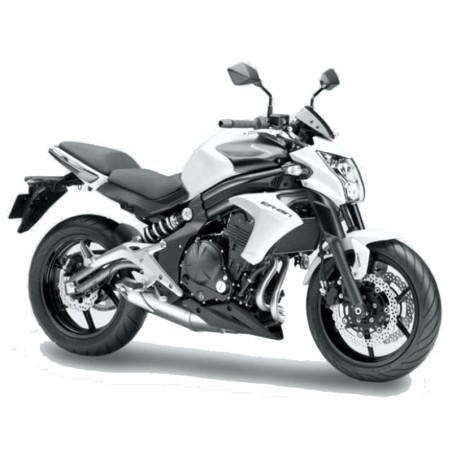


KAWASAKI ER-6n ABS - SERVICE MANUAL - WIRING DIAGRAMS - OWNERS MANUAL
- English Service Manual / Repair Manual, Wiring Diagrams and Owners Manual for motorcycles Kawasaki ER 6n ABS.
CONTENTS:
SERVICE MANUAL
General informations
- Before carrying out an inspection, maintenance or carrying out
- Left side view
- Right side view
- Cassette gearbox
- The atmospheric pressure sensor and the shaft position sensor
- Prefixes for units of measure:
- Temperature unit of measurement:
Periodic maintenance
- Scheduled maintenance must be performed in accordance with
- The following tables list the tightening torque for may
- Internal circlip pliers:
- Fuel system (DFI)
Fuel system (DFI)
- DFI plant
- DFI system wiring diagram
- White page
- Oil pressure gauge, 5 kgf / cm:
- Precautions during maintenance of the DFI system
- General
- NOTE
- General self-diagnosis
- Main throttle valve sensor removal / adjustment
- CAUTION
- Removal / installation
- Removal / installation of the water temperature sensor
- Start the engine and enter the riser 1 self-diagnosis mode
- Speed ??sensor removal / installation
- Vehicle down sensor removal
- Removal / adjustment of the secondary throttle sensor
- Oxygen sensor removal / installation
- Control coil No.1: ignition coil (maintenance code
- Removal / installation of the radiator fan
- Removing the secondary throttle actuator
- Removal / installation of air switching valve
- Oxygen sensor heater removal / installation
- Oxygen sensor removal / installation
- Control flow chart
- CAUTION
- Fuel pressure check
- Removing the fuel pump
- Removal / installation
- Checking the throttle grip play
- Idle speed control
- Removal / installation of the air filter cartridge
- Fuel tank removal
Cooling system
- Bearing installer kit:
- Check for deterioration of the coolant
- Removing the water pump
- Removing the radiator and radiator fan
- Removing the thermostat
- Installing the hose
- CAUTION
Upper part of the engine
- ER650A6F exhaust system
- Pressure gauge for compression control, 20 kgf / cm:
- Removing the air intake valve
- Removing the cylinder head cover
- Removing the timing chain tensioner
- Camshaft removal
- Cylinder compression measurement
- Check valve clearance
- Removing the cylinder
- Throttle body support installation
- DANGER
Clutch
- Clutch locking tool:
- Check the clutch lever free play
- Removing the clutch cover
- Removing the clutch
Engine lubrication system
- Oil pressure gauge, 10 kgf / cm:
- DANGER
- Oil sump removal
- Removal of the oil pressure relief valve
- Oil pump removal
- Oil pressure measurement
- Oil pressure switch removal
Engine removal / installation
- Engine removal
Crankshaft / gearbox
- External snap ring pliers:
- Crankcase separation
- Crankshaft removal
- Removing the balancer
- Gear pedal removal
- Ball and needle bearing replacement
Wheels / tires
- Bearing installer kit:
- Front wheel removal
- Pressure control / regulation
- Hub bearing removal
Transmission organs
- Internal circlip pliers:
- Check the play of the drive chain
- Removing the engine pinion
Brakes
- ABS System
- Internal circlip pliers:
- Brake lever position adjustment
- Removing the front brake caliper
- Removing the front brake pads
- Removing the front brake pump
- Brake disc removal
- Check the brake fluid level
- Removal / installation of brake hose
Suspensions
- Internal circlip pliers:
- Front fork removal
- Spring preload adjustment
- Removing the swingarm
Steering
- Wrench for steering head nuts:
- Steering control
- Removing the steerer tube and bearing
- Handlebar removal
Frame
- Saddle removal
- Removal of the lower fairing
- Side trim removal
- Removing the saddle cover
- Front fender removal
- Chassis check
- Side stand removal
- Frame cover removal
- Removal of rear-view mirrors
Electrical system
- White page
- Pocket tester:
- There is a number of important precautions indispensable in fas
- Wiring check
- Battery removal
- Removing the alternator cover
- Removal / installation of the starter motor clutch
- DANGER
- Removing the starter motor
- This motorcycle uses the daytime running lighting system ed
- Function test of the air switching valve
- Fan motor control
- Instrument panel removal
- Brake light synchronization check
- The box rel [A] contains rel and diodes. The relays and the diodes do not
- Removing the 30 A main fuse
Appendix
- NOTE
OWNERS MANUAL
Specifications
Location Of Parts
Loading And Accessories Information
General Information
- Meter Instruments
- Multifunction Meter
- Key
- Ignition Switch/Steering Lock
- Right Handlebar Switches
- Left Handlebar Switches
- Brake/Clutch Lever Adjusters
- Fuel Tank Cap
- Fuel
- Stand
- Seats
- Helmet Hooks
- Tool Kit
- Rear View Mirror
- Tying Hooks
Break-In
How To Ride The Motorcycle
- Starting the Engine
- Jump Starting
- Moving Off
- Shifting Gears
- Braking
- Anti-lock Brake System (ABS) for models equipped with ABS
- Stopping the Engine
- Stopping the Motorcycle in an Emergency
- Parking
- Catalytic Converter
Safe Operation
- Safe Riding Technique
- Daily Checks
- Additional Considerations for High Speed Operation
Maintenance And Adjustment
Periodic Maintenance Chart
- Engine Oil
- Cooling System
- Spark Plugs
- Kawasaki Clean Air System
- Valve Clearance
- Air Cleaner
- Throttle Control System
- Engine Vacuum Synchronization
- Idle Speed
- Clutch
- Drive Chain
- Brakes
- Brake Light Switches
- Front Fork
- Rear Shock Absorber
- Wheels
- Battery
- Headlight Beam
- Fuses
- General Lubrication
- Cleaning Your Motorcycle
Storage
Environmental Protection
Location Of Labels