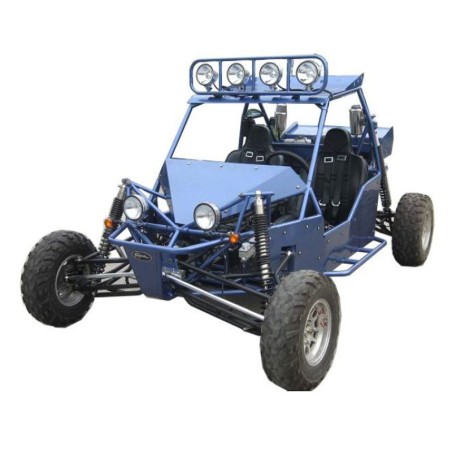


BUGGY JOYNER VIPER 1100 (JNSZ1100SVB) - SERVICE OWNERS & PARTS MANUAL
- English Service Manual, Owners Manual and Spare Parts Catalogue to Buggy Joyner Viper 1100.
CONTENTS:
WARRANTY POLICY
OWNER’S & SERVICE MANUAL
1. Foreword
2. A Few Words About Safety
3. Important Safety Information
Follow The Age Recommendation
Always Wear A Helmet
Drive Off-Road Only
Take Time To Learn & Practice
Be Alert For Off-Road Hazards
Drive Within Your Limits
Don’t Drink And Drive
Never Run Your Go- Kart Indoors.
Keep Away From Moving Parts Of The Off High Way Recreational Vehicle
Skidding Or Sliding
4. Safety Labels
5. Are You Ready To Drive?
Before You Drive Your Off High Way Recreational Vehicle For The First Time, We Urge You To:
Before Each Drive, Be Sure:
Protective Apparel
Drive Training
Age Recommendation
No Alcohol Or Drugs
6. Is Your Vehicle Ready To Drive?
Pre-Drive Inspection
7.Safe Driving Precautions
Off-Road Use Only
Keep Hands And Feet On Controls
Control Speed
Use Care On Unfamiliar Or Rough Terrain
Do Not Perform Stunts
8. Specifications
9. Operation Instruction
Control Pedal
Park Brake Lever And Shift Selector
Switch
Indicating And Gauges
Passengers
10. Maintenance
Chassis Maintenance
Engine Maintenance
Bulb Replacement
PARTS MANUAL
1. Engine
1. Cooling System
2. Cylinder Block
3. Crankshaft
4.Exhaust Manifold
5. Intake System
6. Lubricating Device
7. Cylinder Head
7. Cylinder Head
8. Cover-Valve Chamber
9. Oil Pan
10. Valve Mechanism
10. Valve Mechanism
10. Valve Mechanism
11. Ignition Device
12. Piston And Connecting Rod Device
13. Other Accessory 1
14. Other Accessory 2
2.4t08a2 Transsmission Illustration
1.Case&Accessory
2.Countershaft
3.Input Shaft Assy
4.Shift Fork& Shift- Fork Shaft
5.Shift Control Machanism
6.Driven Gear Assy.Speed Reducer
3.Chassis
1.Frame,Aluminium Board
2.Engine Mount Assy
3.Gear -Shift Mechanism
4.Steering Assy
5.Throttle And Park Assy
6.Parking Brake Assy
8.Front Susp Assy
9.Fuel Tank And Gasoline Pump
10.Muffler
11.Rear Susp Left
12.Rear Susp,Right
13.Cooling Cycle
14.Electical Appliance
15.Fin Assy,Front Cover
16.Seat And Safety Belt
17.Rack Relative Option
18.Fender Relative Option
19.Spotlight Relative Option
20.Long Cobined Handle Option
21.Short Combined Handle Option
22.Big Flag Staff Mount Option
24.Alum Combined Pipe Clamp Option
25.Small Flagstaff Mount Option
26.Shock Absorber Coat Option
27.Tools And Bag Kit Option
28.Envelopment And Foam Cover Option
29. Luxury Absorber Shock Option
WEARING PARTS
1.Body
2.Engine
3.Transmission
4.Standard Part
PREPARATION ATTACH INSTRUCTION
1.Remove Packing
2.Install The Front Suspension Arm
3.Attach Front Shock Absorber
4.Attach Tie Rod End And Front Wheel
4.Attach Tie Rod And Front Wheel
5.Attach The Rear Suspension Arm
6.Attach Drive Shaft
7.Attach Rear Shock Absorber
8.Attach Rear Wheel
9.Check Vehicle
DEALER PRE-DELIVERY INSPECTION