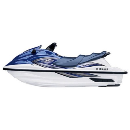


YAMAHA WAVERUNNER XL800 - WORKSHOP, SERVICE, REPAIR MANUAL - WIRING DIAGRAMS - OWNERS MANUAL
- English Service Manual / Repair Manual, Wiring Diagrams and Owners Manual, for jet ski Yamaha WaveRunner XL800.
CONTENTS:
SERVICE MANUAL
Chapter 1 General Information
- Identification Numbers
- Safety While Working
- Special Tools
Chapter 2 Specifications
- General Specifications
- Maintenance Specifications
- Tightening Torques
- Cable and Hose Routing
Chapter 3 Periodic Inspection and Adjustment
- Maintenance Interval Chart
- Control System
- Fuel System
- Oil Injection System/ Power Unit
- Power Unit
- Electrical
- Jet Pump Unit
- General
Chapter 4 Fuel System
- Fuel Cock & Filter
- Choke Cable
- Oil Tank
- Fuel Tank
- Intake Silencer
- Carburetor Unit
- Carburetor
- Fuel Pump
- Oil Pump
Chapter 5 Power Unit
- Exhaust Chamber Assembly
- Exhaust Chamber Joint
- Engine Unit
- Exhaust Manifold
- Reed Valves
- YPVS
- Cylinder Head
- Cylinders
- Pistons
- Starter Motor
- Flywheel Magneto
- Crankcase
- Crankshaft
Chapter 6 Jet Pump Unit
- Reverse Gate
- Nozzle Deflector & Ring
- Impeller Duct, Impeller Housing, and Intake Duct
- Impeller Duct and Drive Shaft
- Transom Plate and Hoses
- Bearing Housing
Chapter 7 Electrical System
- Electrical Components
- Electrical Box
- Electrical Analysis
- Ignition System
- Starting System
- Starter Motor
- Charging System
- YPVS
- YPVS Servomotor
- Indication System
Chapter 8 Hull and Hood
- Handlebar
- QSTS Grip
- Steering Master
- Remote Control Cables and Speed Sensor Lead
- Front Hood
- Steering Master Cover
- Hoses
- Shift Lever
- Seats and Hand Grip
- Exhaust System
- Deck and Hull
- Engine Mount
Chapter 9 Trouble Analysis
Wiring Diagram
OWNERS MANUAL
- Contents
- General Safety And Information
- Features And Functions
- Operation And Riding
- Maintenance And Care
- Troubleshooting And Emergency Procedure
- Index
