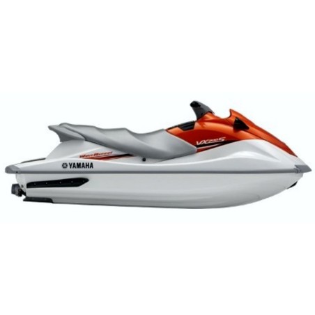


YAMAHA WAVERUNNER VX 700 , VX 700 (F2V) - WORKSHOP, SERVICE, REPAIR MANUAL - WIRING DIAGRAMS
- English Service Manual / Repair Manual and Wiring Diagrams for jet ski Yamaha WaveRunner VX 700 and F2V.
CONTENTS:
General information
- Safety while working
- Rotating part
- Hot part
- Electric shock
- Impeller
- Handling of gasoline
- Ventilation
- Self-protection
- Working with crane
- Handling of heat gun
- Part, lubricant, and sealant
- Handling of sealant
- Special service tool
- Tightening torque
- Non-reusable part
- Disassembly and assembly
- How to use this manual
- Manual format
- Abbreviation
- Adhesive, lubricant, sealant, and thread locking agent
- Symbol
- Special service tool
- Model feature
- Identification number
Specification
- Model data
- Model code
- Dimension and weight
- Performance
- Power unit
- Drive unit
- Fuel and oil requirement
- Battery requirement
- Fuel system technical data
- Fuel system
- Power unit technical data
- Power unit
- Cylinder head assy.
- Crank case assy.
- Jet pump unit technical data
- Jet pump unit
- Electrical technical data
- Ignition system
- Charging system
- Control system
- Starting system
- Meter system
- Specified tightening torque
- Fuel system
- Power unit
- Jet pump unit
- Electrical system
- Hull and hood
- General tightening torque
- Cooling system
- Cable and hose routing
- Starboard bow view
- Top view
- Port view
Maintenance
- Maintenance interval chart
- Periodic service
- Steering system
- Fuel system
- Oil injection system
- Power unit
- Jet pump unit
- Electrical
- Hull and hood
- Lubrication points
Fuel system
- Fuel cock and fuel filter
- Fuel filter check
- Fuel cock check
- Choke cable
- Oil tank
- Oil line check
- Oil level sensor check
- Oil tank check
- Fuel tank
- Check valve check
- Fuel level sensor check
- Fuel tank check
- Fuel filler cap check
- Carburetor unit
- Choke cable and throttle cable installation
- Carburetor assy. check
- Carburetor and fuel pump
- Diaphragm check
- Arm check
- Body assy. check
- Needle valve check
- Jet and carburetor body check
- Fuel pump check
- Fuel filter check
- High and low speed screw adjustment
- Throttle valve synchronization check and adjustment
- Choke valve synchronization check and adjustment
- Carburetor assy. check
- Oil pump
- Oil pump check
- Oil hose check
- Check valve check
- Oil pump air bleeding
Power unit
- Engine unit
- Engine mount
- Engine unit removal
- Engine mount check
- Engine unit installation
- Exhaust ring
- Exhaust chamber assy.
- Exhaust chamber
- Muffler
- Reed valves
- Reed valve check
- Cylinder head
- Cylinder head check
- Cylinder head installation
- Cylinder
- Cylinder check
- Cylinder installation
- Pistons
- Piston pin clip removal and installation
- Piston check
- Piston ring check
- Piston pin and bearing check
- Piston installation
- Flywheel magneto and base assy.
- Starter clutch assy.
- Drive coupling removal and installation
- Flywheel magneto removal and installation
- Drive coupling check
- Flywheel magneto check
- Starter clutch assy. check
- Base assy. installation
- Crankcase
- Crankcase check
- Crankcase installation
- Crankshaft
- Crankshaft check
Jet pump unit
- Intake grate and ride plate
- Jet pump unit
- Jet pump unit removal
- Jet pump unit installation
- Jet thrust nozzle, impeller duct, and impeller housing
- Impeller duct and drive shaft
- Drive shaft removal
- Impeller check
- Impeller housing check
- Drive shaft check
- Drive shaft installation
- Transom plate and hoses
- Bilge strainer check
- Bilge hose check
- Cooling water hose check
- Bearing housing
- Intermediate drive shaft assy.
- Joint removal
- Joint installation
- Driven coupling removal and installation
- Intermediate drive shaft extension removal
- Intermediate drive shaft removal
- Bearing removal
- Driven coupling check
- Bearing and oil seals installation
- Intermediate drive shaft installation
- Intermediate drive shaft extension installation
Electrical system
- Electrical components
- Electrical box
- Electrical analysis
- To measure the peak voltage
- Ignition system
- Ignition coil
- CDI unit
- CDI unit resistance
- Charge coil
- Pickup coil
- Thermoswitch
- Charging system
- Lighting coil
- Rectifier regulator
- Starting system
- Fuse
- Left handlebar switch assy.
- Starter relay
- Starter motor
- Starter motor operation
- Armature
- Front and rear cover
- Brush holder
- Starter motor assembly
- Indication system
- Multifunction meter
- Oil level sensor and oil level warning indicator
- Fuel level meter display and fuel level warning indicator
- Engine overheat warning indicator
- Buzzer
Hull and hood
- Steering pad and handlebar cover
- Handlebar and handlebar switch assy.
- Left handlebar switch assy. and throttle lever assy.
- Throttle cable removal
- Handlebar check
- Left handlebar switch assy. check
- Handlebar assy. installation
- Steering pad and handlebar cover installation
- Front hood
- Service lid installation
- Hinge assy. check
- Hood lock check
- Multifunction meter and engine hatch cover
- Steering master assy.
- Steering master
- Shift lever assy. check
- Bushing check
- Steering arm assy. installation
- Steering cable
- Steering cable installation (steering master end)
- Steering cable installation (jet pump end)
- Seat and handgrip
- Ventilation hose and water separator
- Seat lock check
- Check valve check
- Water separator assy. removal
- Water separator check
- Water separator assy. installation
- Cooling water pilot outlet installation
- Ventilation hose installation
- Exhaust system
- Exhaust system check
- Deck and hull
- Rear section
- Drain plug check
- Spout installation
Troubleshooting
- Engine unit troubleshooting
- Troubleshooting (engine unit, jet pump unit, charging system)
Appendix
- Wiring diagram