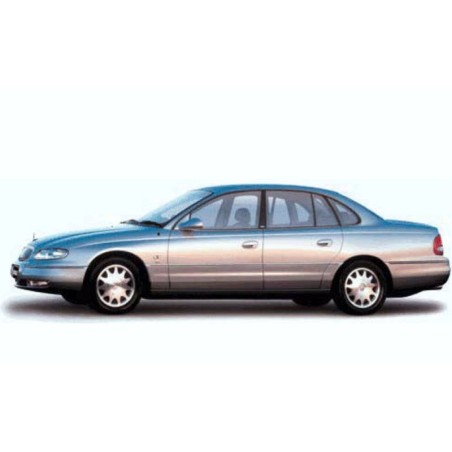


HOLDEN WH STATESMAN AND CAPRICE (1999-2001) - WORKSHOP, SERVICE, REPAIR MANUAL - WIRING DIAGRAMS
- English Service Manual and Wiring Diagrams, to cars Holden WH Statesman and Caprice 1999-2001.
CONTENTS:
INTRODUCTION AND TECH 2
- Section 00 – Cautions And Notes
- Section 0a - General Information
- Section 0a - General Information – Wh With U4b
- Section 0b – Lubrication And Service
- Section 0c - Tech 2
EXTERNAL FITTINGS
- Section 1a1 - Body
- Section 1a2 - Body Dimensions
- Section 1a4 - Rear Compartment Lid
- Section 1a5 - Front And Rear Door Assemblies
- Section 1a6 - Stationary Glass
- Section 1a9 - Exterior Ornamentation
- Section 1b - Sheet Metal
- Section 1c - Radiator Grille
- Section 1d - Bumper Bars
- Section 1f - Sunroof
INTERNAL FITTINGS
- Section 1a3 - Instrument Panel And Console
- Section 1a7 - Seat And Seat Belt Assemblies
- Section 1a8 - Headlining And Rear End Trim
- Section 1e - Cockpit Module
HEATING AND AIR CONDITIONING
- Section 2a - Electronic Climate Control (Ecc) - Principles And Operation
- Section 2b - Electronic Climate Control (Ecc) - Removal And Installation
- Section 2c - Air Conditioning (Ecc) - Servicing And Diagnosis
- Section 2d - Electronic Climate Control (Ecc) - Diagnostics
SUSPENSION, STEERING, BRAKES, WHEELS AND TYRES
- Section 3 - Front Suspension
- Section 4a - Independent Rear Suspension
- Section 5a - Standard Brakes
- Section 5b - Abs & Abs/Etc
- Section 9 - Steering
- Section 10 - Wheels And Tyres
- Section 12l - Anti-Lock Braking & Electronic Traction Control
V6 ENGINE
- Section 6a1 - Engine Mechanical
- Section 6a1 - Engine Mechnical – Wh With U4b
- Section 6b1 - Engine Cooling
- Section 6c1 - Powertrain Management
- Section 6c1 - Powertrain Management – Wh With U4b
- Section 6d1-1 - Charging System
- Section 6d1-2 - Starting System
- Section 6d1-3 - Ignition System
- Section 6e1 - Emission Control
- Section 6f1 - Engine Tune
V8 GEN III ENGINE
- Section 6a3 - Engine Mechanical
- Section 6a3 - Engine Mechnical – Wh With A8a Or U4b
- Section 6b3 - Engine Cooling
- Section 6c3 - Powertrain Management
- Section 6c3 - Powertrain Management – Wh With A8a Or U4b
- Section 6d3-1 - Charging System
- Section 6d3-2 - Starting System
- Section 6d3-3 - Ignition System
- Section 6e3 - Emission Control
- Section 6f3 - Engine Tune
TRANSMISSION AND DRIVE TRAIN
- Section 4b - Final Drive And Drive Shafts
- Section 4c - Propeller Shaft And Universal Joints
- Section 4c - Propeller Shaft And Universal Joints – Wh With U4b
- Section 7c - Hydra-Matic 4l60e Automatic Transmission: General Information
FUEL AND EXHAUST SYSTEM
- Section 8a - Fuel Tank
- Section 8b - Exhaust System
ELECTRICAL SYSTEM
- Section 12a - Battery & Cables
- Section 12b - Lighting System
- Section 12c - Instruments, Wipers/Washers & Horn
- Section 12d - Audio Systems
- Section 12e - Cruise Control
- Section 12f - Theft Deterrent System
- Section 12g - Cellular Mobile Telephone
- Section 12h - Electrically Adjustable Rear Vision Mirrors
- Section 12j-2 - High Series Body Control Module
- Section 12k - Electrically Adjustable Front Seats
- Section 12m - Supplemental Restraint System
- Section 12n - Fuses, Relays And Wiring Harnesses
- Section 12q - Telematics
- Section 12 - Electrical Systems – Wh With U4b
WIRING DIAGRAMS
- Section 12p – Wiring Diagrams
- Section 12p - Wiring Diagrams – Wh With U4b