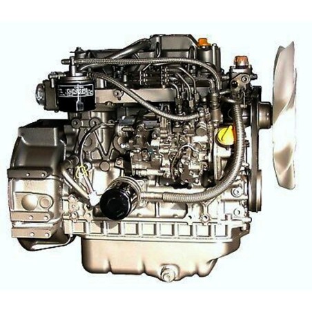

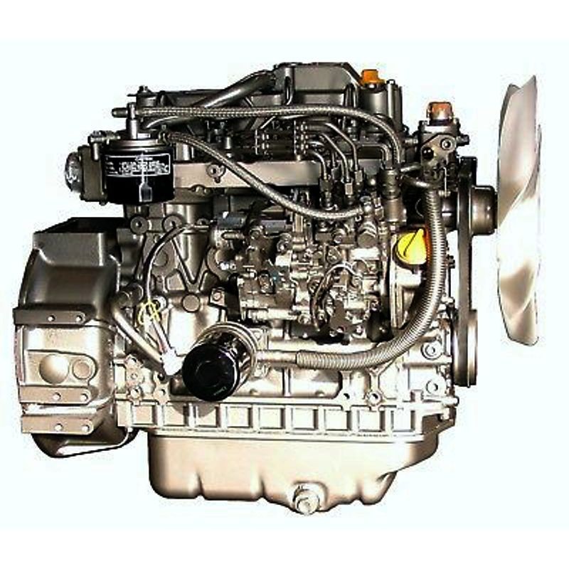
YANMAR 4TNV88, 4TNV88-B, 4TNV88-U ENGINE - WORKSHOP, SERVICE, REPAIR MANUAL
- English Service Manual / Repair Manual, for Yanmar 4TNV88 4TNV88B 4TNV88U Engine.
CONTENTS:
SERVICE MANUAL
-Cover
-Table Of Contents
-Introduction
-Yanmar Warranties
- Yanmar Limited Warranty
- What Is Covered By This Warranty?
- How Long Is The Warranty Period?
- What The Engine Owner Must Do:
- To Locate An Authorized Yanmar Industrial Engine Dealer Or Distributor:
- What Yanmar Will Do:
- What Is Not Covered By This Warranty?
- Warranty Limitations:
- Warranty Modifications:
- Questions:
- Retail Purchaser Registration
- Emission System Warranty
- Yanmar Co., Ltd. Limited Emission Control System Warranty - Usa Only
- Your Warranty Rights And Obligations:
- California
- Manufacturer’s Warranty Period:
- Warranty Coverage:
- Warranted Parts:
- Exclusions:
- Owner’s Warranty Responsibilities:
-Safety
- Safety Statements
- Safety Precautions
-General Service Information
- Component Identification
- Location Of Labels
- Engine Nameplate (Typical)
- Emission Control Regulations
- Epa / Arb Regulations - Usa Only
- Emission Control Labels
- The 97/68/Ec Directive Certified Engines
- Engine Family
- Function Of Major Engine Components
- Main Electronic Control Components And Features
- Function Of Cooling System Components
- Diesel Fuel
- Diesel Fuel Specifications
- Additional Technical Fuel Requirements
- Bio-Diesel Fuels
- Kit Parts List For B20 (Tnv Di Engines)
- Filling The Fuel Tank
- Priming The Fuel System
- Engine Oil
- Engine Oil Specifications
- Service Categories
- Definitions
- Additional Technical Engine Oil Requirements:
- Engine Oil Viscosity
- Checking Engine Oil
- Adding Engine Oil
- Engine Oil Capacity (Typical)
- Engine Coolant
- Engine Coolant Specifications
- Additional Technical Coolant Specifications:
- Alternative Engine Coolant
- Filling Radiator With Engine Coolant
- Engine Coolant Capacity (Typical)
- Specifications
- Description Of Model Number
- Engine Speed Specifications
- Principal Engine Specifications
- 3tnv82a (~ Epa Tier2)
- Engine Service Standards
- Tightening Torques For Standard Bolts And Nuts
- Abbreviations And Symbols
- Abbreviations
- Symbols
- Unit Conversions
- Unit Prefixes
- Units Of Length
- Units Of Volume
- Units Of Mass
- Units Of Force
- Units Of Torque
- Units Of Pressure
- Units Of Power
- Units Of Temperature
-Periodic Maintenance
- Before You Begin Servicing
- Introduction
- The Importance Of Periodic Maintenance
- Performing Periodic Maintenance
- Yanmar Replacement Parts
- Required Epa / Arb Maintenance - Usa Only
- Epa / Arb Installation Requirements - Usa Only
- Periodic Maintenance Schedule
- Periodic Maintenance Procedures
- After Initial 50 Hours Of Operation
- Replace Engine Oil And Engine Oil Filter
- Check And Adjust Cooling Fan V-Belt
- Every 50 Hours Of Operation
- Drain Fuel Filter / Water Separator
- Check Battery
- Every 250 Hours Of Operation
- Drain Fuel Tank
- Replace Engine Oil And Engine Oil Filter
- Check And Clean Radiator Fins
- Check And Adjust Cooling Fan V-Belt
- Check And Adjust The Governor Lever And Engine Speed Control
- Clean Air Cleaner Element
- Every 500 Hours Of Operation
- Replace Air Cleaner Element
- Replace Fuel Filter
- Clean Fuel Filter / Water Separator
- Every 1000 Hours Of Operation
- Drain, Flush And Refill Cooling System With New Coolant
- Adjust Intake / Exhaust Valve Clearance
- Every 1500 Hours Of Operation
- Inspect, Clean And Test Fuel Injectors
- Clean Egr Cooler 4tnv84t-Z, 4tnv98t-Z
- Inspect Crankcase Breather System
- Every 2000 Hours Of Operation
- Check And Replace Fuel Hoses And Engine Coolant Hoses
- Lap The Intake And Exhaust Valves
- Every 3000 Hours Of Operation
- Inspect Turbocharger (Blower Wash As Necessary)
- Inspect, Clean And Test Egr Valve 4tnv84t-Z, 4tnv98t-E, 4tnv98-Z, 4tnv98t-Z
- Inspect And Clean Egr Lead Valve 4tnv84t-Z, 4tnv98t-Z
-Engine
- Before You Begin Servicing
- Introduction
- Cylinder Head Specifications
- Adjustment Specifications
- Cylinder Head
- Intake / Exhaust Valve And Guide
- Push Rod
- Rocker Arm And Shaft
- Valve Spring
- Camshaft And Timing Gear Train Specifications
- Camshaft
- Idler Gear Shaft And Bushing
- Timing Gear Backlash
- Crankshaft And Piston Specifications
- Crankshaft
- Thrust Bearing
- Piston
- Piston Ring
- Connecting Rod
- Connecting Rod Small End
- Connecting Rod Big End
- Tappet
- Cylinder Block Specifications
- Cylinder Block
- Special Torque Chart
- Torque For Bolts And Nuts
- Special Service Tools
- Measuring Instruments
- 2-Valve Cylinder Head
- 2-Valve Cylinder Head Components
- Components Of A Two-Valve Cylinder Head
- Disassembly Of 2-Valve Cylinder Head
- Removing The Glow Plugs
- Removal Of Valve Cover
- Removal Of Rocker Arm Assembly
- Disassembly Of Rocker Arm Assembly
- Removal Of Cylinder Head
- Removal Of Intake / Exhaust Valves
- Removal Of Valve Guides
- Cleaning Of Cylinder Head Components
- Inspection Of Cylinder Head Components
- Inspection Of Push Rods
- Inspection Of Rocker Arm Assembly
- Inspection Of Valve Guides
- Inspection Of Cylinder Head
- Inspection Of Intake And Exhaust Valves
- Inspection Of Valve Springs
- Reassembly Of Cylinder Head
- Reassembly Of Valve Guides
- Reassembly Of Intake And Exhaust Valves
- Reassembly Of Cylinder Head
- Reassembly Of Rocker Arm Reassembly
- Reassembly Of The Valve Cover
- 4-Valve Cylinder Head
- 4-Valve Cylinder Head Components
- Disassembly Of 4-Valve Cylinder Head
- Removal Of Valve Cover
- Removal Of Rocker Arm Assembly
- Disassembly Of Rocker Arm Assembly
- Removal Of Cylinder Head
- Removal Of Intake And Exhaust Valves
- Removal Of Valve Guides
- Cleaning Of Cylinder Head Components
- Inspection Of Cylinder Head Components
- Inspection Of Push Rods
- Inspection Of Rocker Arm Assembly
- Inspection Of Valve Guides
- Inspection Of Cylinder Head
- Inspection Of Intake And Exhaust Valves
- Inspection Of Valve Springs
- Inspection Of Valve Bridges
- Reassembly Of Cylinder Head
- Reassembly Of Valve Guides
- Reassembly Of Intake And Exhaust Valves
- Reassembly Of Cylinder Head
- Reassembly Of Rocker Arm Assembly
- Reassembly Of The Valve Cover
- Measuring And Adjusting Valve Clearance
- 2-Valve Cylinder Heads
- 4-Valve Cylinder Heads
- Crankshaft And Camshaft Components
- Disassembly Of Engine
- Disassembly Of Camshaft And Timing Components
- Removal Of Timing Gear Case Cover
- Checking Timing Gear Backlash
- Measuring Idler Gear-To-Crankshaft Gear Backlash
- Measuring Idler Gear-To-Camshaft Gear Backlash
- Removal Of Timing Gears
- Removal Of Oil Pan
- Removal Of Camshaft
- Removal Of Gear Case Or Front Plate
- Disassembly Of Crankshaft And Piston Components
- Removal Of Pistons
- Removal Of Crankshaft
- Inspection Of Crankshaft And Camshaft Components
- Replacement Of Crankshaft Oil Seals
- Measure Crankshaft Bearing Oil Clearance
- Inspection Of Cylinder Block
- Inspection Of Pistons, Piston Rings And Wrist Pin
- Inspection Of Connecting Rod
- Inspection Of Tappets
- Inspection Of Crankshaft
- Inspection Of Camshaft
- Inspection Of Camshaft Bushing And Bores
- Inspection Of Idler Gear And Shaft
- Honing And Boring
- Reassembly Of Crankshaft And Piston Components
- Reassembly Of Pistons
- Installation Of Crankshaft
- Installation Of Pistons
- Reassembly Of Camshaft And Timing Components
- Installation Of Gear Case Or Front Plate
- Installation Of Camshaft
- Installation Of Timing Gears
- Installation Of Gear Case Cover
- Installation Of Oil Pan
- Final Reassembly Of Engine
- Egr System
- Egr System
- Egr System
- 4tnv98-E, 4tnv98-Z
- 4tnv84t-Z, 4tnv98t-Z
- Inspecting/Cleaning Egr Related Components
- Egr Valve
- Egr Valve Operation Checks
- Cleaning The Egr Valves
- Lead Valves
- Precautions For Installation
- Egr Cooler
- Egr Pipe And Other Connecting Elbows
- Installing Egr Related Components/Parts
-Fuel System
- Before You Begin Servicing
- Introduction
- Fuel Injection Pump
- Stop Solenoid
- Cold Start Device
- Trochoid Fuel Pump
- Electronically Controlled Governor
- Fuel System Specifications
- Special Torque Chart
- Test And Adjustment Specifications
- Special Service Tools
- Measuring Instruments
- Fuel System Diagram
- Fuel System Components
- 2-Valve Cylinder Head
- 4-Valve Cylinder Head
- Fuel Injection Pump
- Removal Of Fuel Injection Pump
- Installation Of Fuel Injection Pump
- Idle Sub Spring Adjustment
- Checking And Adjusting Fuel Injection Timing
- Determining The Fuel Injection Timing Specification
- (6.8 X 2) = 13.6 + 4 = 17.6° Fuel Injection Timing
- Checking Fuel Injection Timing
- Adjusting Fuel Injection Timing
- Fuel Injectors
- Removal Of Fuel Injectors
- 2-Valve Cylinder Head
- 4-Valve Cylinder Head
- Testing Of Fuel Injectors
- Disassembly And Inspection Of Fuel Injectors
- Adjusting Fuel Injector Pressure
- Reassembly Of Fuel Injectors
- Installation Of The Fuel Injectors
- 2-Valve Cylinder Head
- 4-Valve Cylinder Head
- Fuel Injection System (For A Four-Valve Cylinder Head)
-Cooling System
- Before You Begin Servicing
- Introduction
- Cooling System Diagram
- Engine Coolant Pump Components
- Engine Coolant System Check
- Engine Coolant Pump
- Removal Of Engine Coolant Pump
- Disassembly Of Engine Coolant Pump
- Cleaning And Inspection
- Temperature Switch
- Water Temperature Sensor
- Thermostat
- Radiator Cap
- Reassembly Of Engine Coolant Pump
- Installation Of Engine Coolant Pump
-Lubrication System
- Before You Begin Servicing
- Introduction
- Oil Pump Service Information
- Lubrication System Diagram
- Checking Engine Oil Pressure
- Trochoid Oil Pump
- 3tnv82a To 4tnv88 Oil Pump Components
- Disassembly Of Oil Pump
- Cleaning And Inspection
- Check Outer Rotor Outside Clearance
- Outer Rotor To Inner Rotor Tip Clearance
- Check Outer Rotor Side Clearance
- Check Inner Rotor And Gear Boss Clearance
- Reassembly Of Oil Pump
- Trochoid Oil Pump
- 3tnv82a-B, 3tnv88-B, 3tnv88- U, 4tnv88-B4tnv88-U, 3tnv84t-Z, 4tnv84t-Z Oil Pump Components
- Disassembly Of Oil Pump
- Cleaning And Inspection
- Check Outer Rotor Outside Clearance
- Outer Rotor To Inner Rotor Tip Clearance
- Check Outer Rotor Side Clearance
- Check Rotor Shaft Clearance
- Reassembly Of Oil Pump
- Trochoid Oil Pump
- 4tnv94l/98/106 Oil Pump Components
- Disassembly Of Oil Pump
- Cleaning And Inspection
- Check Outer Rotor Outside Clearance
- Outer Rotor To Inner Rotor Tip Clearance
- Check Outer Rotor Side Clearance
- Check Rotor Shaft Clearance
- Reassembly Of Oil Pump
-Turbocharger
- Before You Begin Servicing
- Introduction
- Specifications
- Turbocharger Service Information
- Troubleshooting
- Excessive Exhaust Smoke
- Generates White Smoke
- Sudden Oil Decrease
- Decrease In Output
- Poor (Slow) Response (Starting) Of Turbocharger
- Abnormal Sound Or Vibration
- Turbocharger Components
- Turbocharger Component Functions
- Theory Of Operation
- Turbine
- Compressor
- Bearings
- Compressor Side Sealing Mechanism
- Waste Gate Modulation
- Waste Gate Control
- Washing Procedure
- Periodic Inspection
- Visual Inspection
- Inspection Of Rotor Rotation
- Inspection Of Rotor Play
- Removal Of Turbocharger
- Checking Rotor Play
- To Check Rotor End Play:
- To Check Rotor Run-Out:
- Waste Gate Valve Test
- Waste Gate Actuator Leak Test
- Installation Of Turbocharger
-Starter Motor
- Before You Begin Servicing
- Introduction
- Starter Motor Information
- 3tnv82a To 4tnv88 - Standard And Optional
- Starter Motor Specifications
- Starter Motor Troubleshooting
- Starter Motor Components
- Starter Motor
- Removal Of Starter Motor
- Disassembly Of Starter Motor
- Cleaning And Inspection
- Armature
- Field Coil
- Magnetic Switch
- Pinion Clutch Assembly
- Reassembly Of Starter Motor
- Check Pinion Projection Length
- No-Load Test
- Installation Of Starter Motor
-Alternator
- Before You Begin Servicing
- Introduction
- Dynamo And Alternator Information
- 3tnv82a To 4tnv106t - Standard And Optional Dynamos
- 3tnv82a To 4tnv106t - Standard And Optional Alternators
- Alternator Specifications
- Dynamo Specifications
- Alternator Troubleshooting
- Alternator Components
- Alternator Wiring Diagram
- Alternator Standard Output
- Alternator
- Removal Of Alternator
- Disassembly Of Alternator
- Reassembly Of Alternator
- Installation Of Alternator
- Dynamo Component Location
- Dynamo Wiring Diagram
- Operation Of Dynamo
- Dynamo Standard Output
- Testing Of Dynamo
- Testing Stator Coil Continuity
- Testing Stator Coil Short-To-Ground
- Testing Dynamo Regulated Output
- Dynamo
- Removal Of Dynamo
- Disassembly Of Dynamo
- Reassembly Of Dynamo
- Installation Of Dynamo
-Electronic Control System
- Engines Available With The Electronic Control System
- Before You Begin Servicing
- Introduction
- Electronic Control System
- Electronic Control Harness Connections
-Electric Wiring
- Electric Wiring Precautions
- Electrical Wire Resistance
- Battery Cable Resistance
- Electrical Wire Sizes - Voltage Drop
- Conversion Of Awg To European Standards
-Failure Diagnosis
- Special Service Tools
- Troubleshooting By Measuring Compression Pressure
- Compression Pressure Measurement Method
- Measured Value And Troubleshooting
- Quick Reference Table For Troubleshooting
- Failure Diagnostic List
- Electrical Wiring
-Back Cover
TROUBLESHOOTING MANUAL
-Cover
-Failure Diagnosis
-Dtcs (Diagnostic Trouble Codes) General Description
- Dtc Code List
- Description Items
- Analog Input Related Failures
- Rack Position Sensor
- Accelerator Sensor
- Spare Accelerator Sensor (Option)
- Atmospheric Pressure Sensor (Option)
- Ecu Temperature Sensor
- Cooling Water Temperature Sensor
- Sensor 5v
- Power Supply Voltage
- Pulse Sensor Related Failures
- Speed Sensor
- Spare Speed Sensor (Option)
- Engine Rotational Speed
- Contact Output Related Failures
- Rack Actuator Relay
- Start Assist Relay
- Csd Solenoid Valve
- Egr Valve
- Contact Input Related Failures
- Oil Pressure Related Failures
- Battery Charge Related Failures
- Water Temperature Switch
- Air Cleaner Switch
- Oil-Water Separator Switch
- Actuators Etc.
- Rack Actuator
- Engine
- E-Ecu Internal Errors
- Can Communication
- Immobilizer
-Method And Procedure Of Failure Diagnosis
- Description Items
- E-Ecu Pin Layout Diagram
- How To Use The 2g Eco-Checker Harness
- Analog Input Related Failures
- Rack Position Sensor
- Accelerator Sensor
- Foot Pedal
- Spare Analog (Spare Accelerator Sensor, Atmospheric Pressure Sensor)
- Pulse Accelerator
- Ecu Temperature Sensor
- Cooling Water Temperature Sensor
- Sensor 5v
- Pulse Sensor Related Failures
- Speed Sensor
- Spare Speed Sensor
- Contact Output Related Failures
- Rack Actuator Relay
- Start Assist Relay
- Csd Solenoid Valve Coil
- Egr Valve
- Contact Input Related Failures
- Actuator Related Failures
- Rack Actuator
- Ecu Internal And Communication Errors
- Ecu Internal Errors
- Main Relay
- Can Communication
- Immobilizer
- Failure Indicator Lamp Flashing Pattern
-Using The Failure Indicator For Failure Diagnosis
- Flashing Patterns Of The Failure Indicator
-Factor Analysis
- 2g-Type Eco-Governor Speed-Fluctuation Factor Analysis
-Back Cover