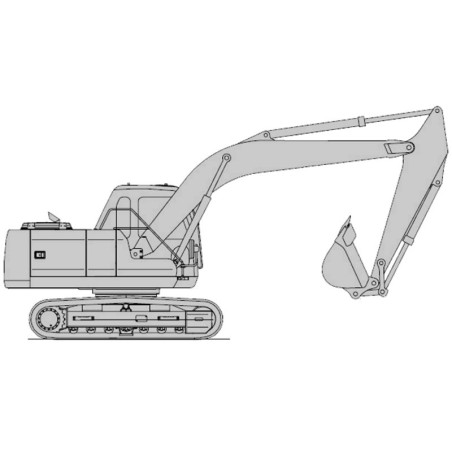
Daewoo Solar S130LC-V Excavator Service & Maintenance Manual
Workshop, service or technical reference material covering the systems actually listed in the original document index. Separate wiring diagram volumes are not implied by a general electrical chapter.
Technical areas in the source: engine and powertrain, transmissions and driveline, brakes and steering, hydraulic systems, electrical circuits and components.
Examples from the original contents: Track Excavator Safety S0102000; Torque Values for Split Flanges; Power Mode Valve; Control Valve Drawing and Hydraulic Circuit.
Languages identified in the original listing: English. Individual documents may use different languages.
Original technical index
- CONTENTS:
- SAFETY
- - Track Excavator Safety S0102000
- -- To the Operator of a Daewoo Excavator
- -- Learn the Signal Words Used with the Safety Alert Symbol
- -- General Safety Essentials
- -- Accessory Applications
- -- Lifting Capacity Rating Configuration
- -- Location of Safety Labels
- -- Summary of Safety Precautions for Lifting in Digging Mode
- -- Unauthorized Modifications
- -- Work-site Precautions
- -- Attachment Precautions
- -- Avoid High-voltage Cables
- -- Before Starting-Dig, Contact Authorities
- -- Be Aware of Height Obstacles
- -- Use Care on Loose Support
- -- Use Solid Support Blocking
- -- Overhangs Are Dangerous
- -- Sloping Terrain Requires Caution
- -- Stay Alert for People Moving through the Work Area
- -- Be Aware of and Conform-Local Regulations
- -- Operation
- -- Operate While Seated at the Operator’s Station ONLY
- -- Before Starting the Engine
- -- Never Use Ether Starting Aids
- -- Mounting and Dismounting
- -- Observe General Safety Rules
- -- Engine Ventilation
- -- Asbestos Dust Hazard Prevention
- -- Take Time-Provide Good Visibility
- -- Fuel, Oil and Hydraulic Fluid Fire Hazards
- -- Boost Starting or Charging Engine Batteries
- -- Travel Controls May Produce Reversed Operations
- -- Keep "Pinch Point" Areas Clear - Use Caution in Reverse & Swing
- -- Travel Precautions
- -- Operate Carefully on Snow and Ice and in Very Cold Temperatures
- -- Parking the Machine
- -- Shutdown Control Functions
- -- Equipment
- -- Rough Operation May Require Use of Certified Safety Equipment
- -- Install Additional Safety Equipment If Conditions Require
- -- Movement Alarms
- -- Seat Belts Should Be Used at All Times
- -- Window Glass Breaking Tool
- -- Keep a Fire Extinguisher at Hand
- -- Maintain Standard Safety Equipment in Good Condition
- -- Safety-critical Parts Must Be Replaced Periodically
- -- Hydraulic Cylinder Seals Require Periodic Replacement
- -- High Pressure Hydraulic Lines Can Store a Great Deal of Energy
- -- The Operator’s Cab and Turntable Deck Should Be Kept Clean
- -- Wear Eye Protection and Safety Clothing
- -- Breathing Masks, Ear Protection May Be Required
- -- Battery Electrolyte and Explosive Gases Can Be Lethal
- -- Disconnect Batteries for Electrical Service Before Electrical Welding
- -- Use Low Heat Portable Lighting
- -- Maintenance
- -- Use Warning Tag Control Lockout Procedures During Service
- -- Do not Run the Engine If Repairs or Work Is Being Performed Alone
- -- Always Use Adequate Equipment Supports and Blocking
- -- Do not Work on Hot Engines or Hot Cooling or Hydraulic Systems
- -- Cool-down Is Required Prior-Radiator or Reservoir Checks
- -- Pressurized Hydraulic Oil Fluid Leaks Can Be Dangerous
- -- Obtain immediate medical attention if pressurized oil pierces the skin.
- -- Use Correct Replacement Fasteners Tightened-Proper Torque
- -- Dispose of All Petroleum-based Oils and Fluids Properly
- -- Track Tension Adjustments Require Caution
- -- Shipping and Transportation
- -- Obey State and Local Over-the-Road Regulations
- -- Lifting With Sling
- SPECIFICATIONS
- - Specifications for Solar 130LC-V S0206000
- -- General Description
- -- General Dimensions
- -- Dimensions and Working Range
- -- General Specifications
- -- Engine Performance Curves (Per KS-R1004 Standard)
- -- Approximate Weight of Workload Materials
- -- Performance Tests
- -- Excavator Performance Standards
- -- Test Conditions
- -- Travel Speed and Travel Motor Balance (Steering Deviation) Tests
- -- Cylinder Performance Tests
- GENERAL MAINTENANCE
- - General Maintenance Procedures S0302000
- -- Welding Precautions and Guidelines
- -- Hydraulic System - General Precautions
- -- Maintenance Service and Repair Procedure
- -- General Precautions
- -- Hydraulic System Cleanliness And Oil Leaks
- -- Maintenance Precautions for Hydraulic System Service
- -- Oil Leakage Precautions
- -- Cleaning and Inspection
- -- Genral Guidelines
- -- Bearing inspection
- - Standard Torques S0309000
- -- Torque Values for Standard Metric Fasteners
- -- Torque Values for Standard U.S. Fasteners
- -- Type 8 Phosphate Coated Hardware
- -- Torque Values for Hose Clamps
- -- Torque Values for Split Flanges
- -- Torque Wrench Extension Tools
- -- Torque Multiplication
- -- Other Uses for Torque Wrench Extension Tools
- -- Tightening Torque Specifications (Metric)
- UPPER STRUCTURE
- - Cab S0402000
- -- Removal
- -- Installation
- -- Window and Gasket Replacement
- -- Falling Object Protective Structures (F.O.P.S.)
- - Counterweight S0403000
- -- General
- -- Removal
- -- Installation
- - Fuel Tank S0405000
- -- General Description
- -- Parts List
- -- Specifications
- -- Removal
- -- Installation
- -- Start-up Procedures
- - Swing Bearing S0407000
- -- Swing Bearing Maintenance
- -- Operating Recommendation
- -- Measuring Swing Bearing Axial Play
- -- Measuring Bearing Lateral Play
- -- Swing Bearing Basic Operation
- -- Rebuilding Swing Bearing
- - Swing Reduction Gearbox S0408020
- -- General Description
- -- Theory of Operation
- -- Parts List
- -- Special Tools and Materials
- -- Special Tools
- -- Troubleshooting, Testing and Adjustment
- -- Removal
- -- Disassembly
- -- Reassembly
- -- Installation
- LOWER STRUCTURE AND CHASSIS
- - Track Assembly S0505050
- -- General Description
- -- Track Tension
- -- Cleaning and Inspection (Wear Limits and Tolerances)
- -- Track Shoes and Links
- -- Parts List
- -- Track Removal
- -- Track Installation
- -- Front Idler Roller
- -- Parts List
- -- Front Idler Roller Disassembly
- -- Front Idler Roller Reassembly
- -- Lower Roller
- -- Parts List
- -- Lower Roller Removal
- -- Lower Roller Disassembly
- -- Lower Roller Reassembly
- -- Lower Roller Installation
- -- Upper Roller
- -- Parts List
- -- Upper Roller Removal
- -- Upper Roller Disassembly
- -- Upper Roller Reassembly
- -- Track Spring and Track Adjusting Cylinder
- -- Parts List
- ENGINE AND DRIVE TRAIN
- - Air-Conditioner S0605010
- -- General Description
- -- Refrigerant Circulation
- -- Control Panel
- -- Control Specifications
- -- Temperature Level Control and Display
- -- Air Discharge According-Path Selection
- -- Air-conditioning System Circuit Diagram
- -- Troubleshooting
- -- Refrigerant System Repairs
- -- Refrigerant Safe Handling Procedures
- -- Repair and Replacement Procedure
- -- Refrigerant Recovery
- -- Vacuuming Refrigerant System
- -- Leakage Check
- -- Refrigerant Charging
- -- Inspecting System For Leakage
- HYDRAULICS
- - Hydraulic System Troubleshooting, Testing and Adjustment S0702050
- -- Hydraulic System - General Notes
- -- Hydraulic Schematic
- -- General Notes
- -- Operation of Working Components
- -- Boom Operating Circuit
- -- Boom Up Circuit
- -- Boom Down Circuit
- -- Arm Operating Circuit
- -- Arm Crowd Circuit
- -- Arm Dump Circuit
- -- Bucket Operating Circuit
- -- Bucket Crowd Circuit
- -- Bucket Dump Circuit
- -- Swing Operating Circuit
- -- Right Swing Operating Circuit
- -- Left Swing Operating Circuit
- -- Swing Relief Valve and Make-up Valve
- -- Travel Operating Circuit
- -- Forward Travel Circuit
- -- Reverse Travel Circuit
- -- Procedural Troubleshooting Baseline Recommendations
- -- Initial Checks and Tests-Establish Operating Condition of the Excavator
- -- Pilot Pressure
- -- Adjustment and Testing
- -- Power Mode Valve
- -- Current Signal and Hydraulic Pressure Adjustments
- -- Boom/Swing Priority Valve
- -- Control Valve Pressure and Current Adjustments
- -- Pressure Up Valve
- -- Checks and Adjustments
- -- Pump Input Power Control
- -- Pump Regulator Adjustment
- -- Flow Meter and Flow Meter Kit Installation and Testing
- -- Swing System Troubleshooting
- -- Precautions/Initial Checks
- -- Swing Relief Valve Checking and Adjustment
- -- Troubleshooting – Swing Gearbox
- -- Troubleshooting – Hydraulic Problems
- -- Troubleshooting – Control Valve
- -- Troubleshooting – Travel Control Valve
- -- Troubleshooting – Joystick Control Valve
- - Accumulator S0703000
- -- General Description
- -- Specifications
- -- Accumulator Charging
- -- Charging the Accumulator with Nitrogen
- - Center Joint (Swivel) S0704020
- -- General Description
- -- Parts List
- -- Troubleshooting, Testing and Adjustment
- -- Inspection
- -- Testing
- -- Disassembly
- -- Reassembly
- - Cylinders S0705000
- -- General Description
- -- Theory of Operation
- -- Parts List
- -- Special Tools and Materials
- -- Piston Nut
- -- Piston Jig
- -- Disassembly
- -- Reassembly
- - Swing Motor S0707220
- -- General Description
- -- Theory of Operation
- -- Swing Motor Anti-cavitation Make-up Valve
- -- Relief Valve
- -- Swing Brake Operation
- -- Parts List
- -- Special Tools
- -- Disassembly
- -- Cleaning and Inspection (Wear Limits and Tolerances)
- -- Reassembly
- - Travel Motor (With Gearbox) S0707340
- -- General Description
- -- Theory of Operation
- -- Travel Motor and Reduction Gearbox Assembly
- -- Travel Motor Parts List
- -- Travel Reduction Gearbox Parts List
- -- Travel Motor Special Tools
- -- Disassembly
- -- Repair Notes
- -- Travel Motor and Reduction Gear Disassembly
- -- Hub and Spindle
- -- Ball Bearing, RV Gear Assembly and Pin
- -- Ball Bearing
- -- Cleaning and Inspection (Wear Limits and Tolerances)
- -- Reassembly
- -- Travel Motor Reassembly
- -- Torques
- -- Travel Motor Rear Flange Reassembly
- - Main Pump (With Regulator) S0708340
- -- General Description
- -- Gear (Pilot) Pump
- -- Relief Valve
- -- Pump Regulator Description
- -- Horsepower Control
- -- Power Shift Control
- -- Negative Oil Discharge (Pump Bypass) Control
- -- Pump Regulator Operation
- -- Pump Output Decrease
- -- Pump Discharge Decrease
- -- Pump Discharge Increase
- -- Horsepower Control
- -- Overload Protection
- -- Regulator Adjustment
- -- Pump Input Power Control Adjustment
- -- Parts List
- -- Specifications
- -- Hydraulic Pump Performance Characteristics
- -- Troubleshooting, Testing and Adjustment
- -- Main Pump
- -- Disassembly
- -- General Disassembly
- -- Main Pump Disassembly
- -- Pump Regulator Disassembly
- -- Cleaning and Inspection (Wear Limits and Tolerances)
- -- Reassembly
- -- Pump Regulator Reassembly
- -- Main Pump Reassembly
- - Main Control Valve S0709420
- -- Control Valve Operation
- -- Swing Priority Circuit
- -- Arm Priority Circuitry
- -- Bucket (Junction) Circuitry
- -- Straight Travelling Circuit
- -- Plunger Replacement
- -- Main Relief Valve
- -- Overload Relief Valve
- -- Arm Load Holding Valve
- -- Boom Load Holding Valve
- -- Arm Regeneration
- -- Foot Relief Valve
- -- Parts List
- -- Specifications
- -- Control Valve Drawing and Hydraulic Circuit
- -- Disassembly and Reassembly
- -- General Disassembly
- -- General Reassembly
- -- Main Plunger Element - Disassembly and Assembly
- -- Tool
- -- Main Relief Valve
- -- Main Relief Valve Adjustment
- -- Overload Relief Valve
- -- Overload Relief Valve [BM UP]
- -- Arm Load Holding Valve
- -- Boom Load Holding Valve
- -- Arm Regeneration Valve
- -- Foot Relief Valve
- -- Center Bypass Valve (CB Valve)
- -- ARm Parallel Switch Valve
- -- Tool
- -- Swing Priority Valve
- -- Boom Unity Check Valve
- -- Straight Travel Selector Valve
- -- Check Valve - Locations
- -- Check Valve
- - Remote Control Valve (Work Lever / Joystick) S0709450
- -- General Description
- -- Theory of Operation
- -- Parts List
- -- Specifications
- -- Hydraulic Specifications
- -- Special Tools
- -- Disassembly
- -- Reassembly
- - Travel Control Valve (RCV8C4015A) S0709800
- -- General Description
- -- Theory of Operation
- -- Parts List
- -- Specifications
- -- Torque Table
- -- Special Tools and Materials
- -- Special Tools
- -- Troubleshooting, Testing and Adjustment
- -- Disassembly
- -- Cleaning and Inspection (Wear Limits and Tolerances)
- -- Reassembly
- - Hydraulic Schematic (S130LC-V) S0792040
- -- General Description
- -- SOLAR 130LC-V
- ELECTRICAL SYSTEM
- - Electrical System S0802060
- -- Troubleshooting - Electrical System
- -- Wiring Harness Illustrations
- -- Overview
- -- Electric Supply System
- -- Engine Starting Circuit
- -- Operation During Start Process
- -- Operation After Start Process
- -- Engine Preheating System
- -- Engine Stop System
- -- Charging System
- -- Monitoring System
- -- Instrument Panel
- -- Function Check
- -- Monitoring System Schematic
- -- Operation
- -- Instruments
- -- Mode Select Switch
- -- Pilot Lamp
- -- Initial Operation
- -- Electronic Hydraulic Control System (Epos - V)
- -- Power Mode Control
- -- Operation
- -- Power Mode Control - Circuit Diagram
- -- Work Mode Control
- -- Operation
- -- Work Mode Control - Circuit Diagram
- -- Engine Control System
- -- Engine Control Motor
- -- Engine Control Dial
- -- Engine Control Circuit Diagram
- -- Automatic Deceleration Control (Auto Idle Control)
- -- Engine Overheat Protection System
- -- Power Boost Mode
- -- Operation
- -- Power Boost Control - Circuit Diagram
- -- Automatic Travel Speed Control
- -- Automatic Travel Speed Control - Circuit Diagram
- -- Engine Control Device - Adjustment
- -- Self-diagnostic Function
- -- EPOS-V Controller
- -- Engine Throttle Controller
- - Electrical Schematic (S130LC-V) S0892040
- -- General Description
- -- Solar 130LC-V
- ATTACHMENTS
- - Boom and Arm S0902030
- -- Front Attachment Pin Specifications
- -- Front Attachment - Removal and Installation
- -- Arm Removal Procedure
- -- Boom Removal Procedure
- -- Installation
- -- Arm Installation Procedure
- -- Boom Installation Procedure
- -- Start-up Procedures
- - Bucket S0904000
- -- Bucket Tooth Inspection and Replacement
- -- Shimming Bucket Linkage
- -- Bucket Attachment, Removal and Reversal
- -- Detaching the Bucket
- -- Attaching The bucket
- -- Reversing the Bucket