- New


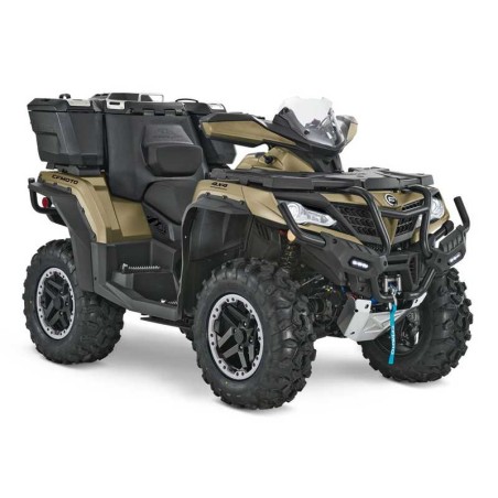
CFMOTO CFORCE 1000 (2021-2024) - SERVICE MANUAL - WIRING DIAGRAMS
- English Service Manual / Repair Manual and Wiring Diagrams for vehicles Cfmoto Cforce 1000 (2021 to 2024).
CONTENTS:
2021-2022
A.1 Chapter Index
- A.2 Foreword
01 Maintenance Information
- 1.1 Precaution
- 1.2 Location Of Vin/Ein
- 1.3 Main Specification
- 1.4 Specification
- 1.5 Tighten Torque
- 1.6 Grease And Sealant
- 1.7 Cable, Brake System And Cooling System
02 Body Covering Parts
- 2.1 Maintenance Information
- 2.2 Tighten Torque:
- 2.3 Seat Assy, Air Filter Cover Assy, Shifting Cover, Side Cover...
- 2.4 Front/Rear Rack Cover, Front/Rear Rack, Handlebar Cover...
- 2.5 Front Lower Panel, Front License Plate, Front Bumper Block...
- 2.6 Front Flare Fender Lh/Rh, Front Upper Inner Fender Lh/Rh...
- 2.7 Front/ Mid/ Rear Lower Panel, Front Suspension Panel Lh/Rh...
- 2.8 Seat Belt (Eu 167)
03 Periodic Inspection And Adjustment
- 3.1 Maintenance Information
- 3.2 Maintenance Period
- 3.3 Steering Column And Brake System
- 3.4 Front Wheel
- 3.5 Suspension System
- 3.6 Shifting Mechanism
- 3.7 Fuel System
- 3.8 Throttle Inspection
- 3.9 Cooling System
- 3.10 Lighting
- 3.11 Selective Shock Absorber View
- 3.12 Shock Absorber Selection
04 Alongside Engine
- 4.1 Maintenance Information
- 4.2 Tightening Torque
- 4.3 Fuel System
- 4.4 Fuel System
- 4.5 Intake System
- 4.6 Exhaust System
- 4.7 Cooling System
- 4.8 Engine Removal And Installation
05 Engine
- 5.1 Maintenance Information
- 5.2 Intake Pipe, Cylinder Head And Cylinder Body
- 5.3 Crankcase, Crankshaft And Gears
- 5.4 Cvt Drive
- 5.5 Engine Lubrication System
- 5.6 Engine Start System
- 5.7 Intake System
- 5.8 Cooling System
- 5.9 Electrical System
- 5.10 Troubleshooting
06 Vehicle Chassis
- 6.1 Maintenance Information
- 6.2 Troubleshooting
- 6.3 Wheels
- 6.4 Brake System
- 6.5 Suspension System
- 6.6 Steering System
- 6.7 Front And Rear Gear Case
- 6.8 Drive Shaft
07 Signal And Lighting System
- 7.1 Maintenance Precautions
- 7.2 Troubleshooting
- 7.3 Indicator Light
- 7.4 Bulb Replacement
- 7.5 Ignition Switch
- 7.6 Handle Bar Switch
- 7.7 Brake Light Switch
- 7.8 Horn
- 7.9 Fuel Pump
- 7.10 Alarm
Starter Wiring Diagram
Efi Wiring Diagram
Wiring Diagram North America
Wiring Diagram Eu V
2023-2024
01 Maintenance Information
- 1.1 Precautions
- 1.2 Location Of Vin/Ein
- 1.3 Main Specification
- 1.4 Specification
- 1.5 Tighten Torque
- 1.6 Grease And Sealant
- 1.7 Cable, Brake System And Cooling System
02 Body Covering Parts
- 2.1 Maintenance Information
- 2.2 Tighten Torque:
- 2.3 Seat Assy, Air Filter Cover Assy, Shifting Cover, Side Cover...
- 2.4 Front/Rear Rack Cover, Front/Rear Rack, Handlebar Cover...
- 2.5 Front Lower Panel, Front License Plate, Front Bumper Block...
- 2.6 Front Flare Fender Lh/Rh, Front Upper Inner Fender Lh/Rh....
- 2.7 Front/ Mid/ Rear Lower Panel, Front Suspension Panel Lh/Rh...
- 2.8 Seat Belt(Eu 167)
03 Periodic Inspection And Adjustment
- 3.1 Maintenance Information
- 3.2 Maintenance Schedules
- 3.3 Steering Column And Brake System
- 3.4 Front Wheel
- 3.5 Suspension System
- 3.6 Shifting Mechanism
- 3.7 Fuel System
- 3.8 Throttle Inspection
- 3.9 Cooling System
- 3.10 Lighting
- 3.11 Selective Shock Absorber View
- 3.12 Shock Absorber Selection
04 Alongside Engine
- 4.1 Maintenance Information
- 4.2 Fuel System
- 4.3 Fuel System
- 4.4 Intake System
- 4.5 Exhaust System
- 4.6 Cooling System
- 4.7 Engine Removal And Installation
05 Engine
- 5.1 Maintenance Information
- 5.2 Precautions
- 5.3 Intake Pipe, Cylinder Head And Cylinder Body
- 5.4 Crankcase, Crankshaft And Gears
- 5.5 Cvt Drive
- 5.6 Engine Lubrication System
- 5.7 Engine Start System
- 5.8 Intake System
- 5.9 Cooling System
- 5.10 Electrical / Efi System
- 5.11 Troubleshooting
06 Vehicle Chassis
- 6.1 Trouble Shooting
- 6.2 Wheels
- 6.3 Brake System
- 6.4 Suspension System
- 6.5 Steering System
- 6.6 Front And Rear Gear Case
- 6.7 Drive Shaft
07 Signal And Lighting System
- 7.1 Maintenance Precautions
- 7.2 Troubleshooting
- 7.3 Indicator Light
- 7.4 Bulb Replacement
- 7.5 Ignition Switch
- 7.6 Handle Bar Switch
- 7.7 Brake Light Switch
- 7.8 Horn
- 7.9 Fuel Pump
- 7.10 Alarm
Starter Wiring Diagram
Efi Wiring Diagram
Wire Diagram North America
Wire Diagram Eu V