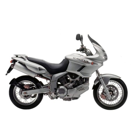


CAGIVA NAVIGATOR - WORKSHOP, SERVICE, REPAIR MANUAL
- English Service Manual, to Cagiva Navigator
CONTENTS:
GENERAL DESCRIPTION A-1
- Instrument panel A-4
- Dimensions and weight A-3
- Electrical system A-4
- Engine unit A-3
- Fuel/oil/engine coolant/fork oil capacity A-4
- Wheels and brakes A-4
- Front suspension A-4
- Rear suspension A-4
- Frame A-4
- Transmission A-3
MAINTENANCE B-1
- Spark plugs B-7
- Transmission chain B-21
- Cooling system B-19
- Compression test B-27
- Oil pressure check B-28
- Technical data B-29
- Air filter B-6
- Brakes B-23
- Clutch B-19
- Throttle cable play B-18
- Valve clearance B-10
- Engine oil and oil filter B-16
- Maintenance and tuning B-4
- Tyres B-26
- Oil pressure test procedure B-28
- Compression test procedure B-27
- Tickover B-17
- Balancing of the carburettors B-18
- Fuel tank removal B-4
- Steering B-26
- Fuel tubing B-16
AIR INTAKE AIR INJECTION SYSTEM C-1
- Air intake system – technical characteristics C-20
- FI system – technical characteristics C-9
- Malfunction codes C-30
- Injection time compensation (volume) C-10
- Connectors/couplings C-3
- Injection stop check C-10
- Fuel injection check C-67
- Fuel pump check C-49
- Fuel pressure check C-48
- Butterfly body C-52
- FI system diagnostics C-28
- ECM/various sensors C-4
- ECM (FI unit test) C-14
- Auto-diagnostic function C-24
- Security function C-27
- Fuses C-4
- Throttle lever play C-72
- Throttle position sensor adjustment (TPS) C-72
- Fuel injector C-12
- Carburettor system C-64
- Dealer mode C-25
- Electric fuel pump C-11
- FI system – position of the parts C-21
- Maintenance precautions C-3
- Electrical system test procedures C-5
- Auto-diagnostic procedure C-29
- Cleaning the carburettor C-59
- Throttle cable adjustment C-73
- Choke adjustment C-68
- Fuel pressure adjustment C-12
- Butterfly body removal C-53
- FI system electrical diagram C-23
- FI system diagram C-22
- Sensors C-16
- Sensors C-74
- Balancing of the carburettors C-69
- Injection synchronisation C-15
- Fuel pump control system C-13
- Incoming fuel feed system C-11
- Carburettor disassembly C-56
- Carburettor disassembly C-60
- Air filter disassembly C-51
- Use of testers C-8
ENGINE D-1
- Camshaft/cylinder head D-81
- Cover/gearchange/crankshaft/connecting rod D-151
- Cylinder/piston D-105
- Engine components that can be removed without removing the engine D-3
- Cylinder/piston test D-108
- Camshaft/cylinder head check and maintenance D-90
- Seat bearings check and maintenance D-163
- Gearchange pre-selector assembly check and maintenance D-146
- Clutch cover/water pump check and maintenance D-125
- Clutch/disengage assembly check D-117
- Timing system description D-83
- Bowl filter/oil pressure regulator D-172
- Oil filter D-177
- Clutch D-114
- Oil spray/piston oil cooling D-177
- Primary drive gear/ N° 1 intermediate gear shaft timing
- pinion sprocket D-129
- Camshaft installation D-102
- Crankshaft/connecting rod/gearbox installation D-168
- Clutch disengagement device installation D-122
- Clutch installation D-119
- Gearchange pre-selector group installation D-148
- Engine/frame installation D-13
- Piston/cylinder installation D-111
- Water pump/clutch cover installation D-127
- Oil pressure switch/oil cooler D-175
- Water pump/clutch cover D-123
- Oil pump D-170
- Gearchange pre-selector D-143
- Oil pressure D-177
- Crankshaft thrust play adjustment D-167
- Camshaft removal D-88
- Cylinder/piston removal D-106
- Clutch disengagement device removal D-116
- Engine removal and installation D-4
- Clutch removal D-115
- Gearchange pre-selector group removal D-144
- Starter motor removal D-142
- Water pump/clutch cover removal D-124
- Timing synchronisation diagram D-86
- Engine lubrication system diagram D-178
- Engine lubrication system D-169
- Engine lubrication system D-179
- Engine disassembly/assembly D-20
- Timing distribution table D-87
SUSPENSION AND WHEELS E-1
- Removal/check of the rear suspension compensator assembly E-21
- Front fork assembly E-12
- Assembly of the rear suspension compensator assembly E-23
- Support tube sliding assembly - reassembly E-9
- Steering assembly E-16
- Spring pre-load adjustment E-21
- Front fork assembly overhaul E-7
- Front wheel E-3
- Rear wheel E-17
- Support tube sliding assembly removal E-8
- Handlebar removal E-13
- Steering removal E-13
- Front suspension E-6
- Chain, crown wheel and pinion wheel overhaul E-18
- Rear wheel E-17
- Rear fork removal E-23
- Rear suspension E-20
- Frame E-25
BRAKES F-1
- Brake pump check F-11
- Brake pump check F-15
- Brake pad wear check F-4
- Brake discs F-4
- Front brake F-3
- Rear brake F-3
- Brake pump assembly and installation F-11
- Brake pump assembly and installation F-15
- Front brake pincer removal and reassembly F-8
- Rear brake pincer removal and reassembly F-9
- Front brake pump removal and reassembly F-10
- Rear brake pump removal and reassembly F-13
- Brake fluid substitution F-6
- Bleeding air from the braking circuit F-7
ELECTRICAL SYSTEM G-1
- Maintenance precautions G-5
- Initial charge G-38
- Ignition/side stand security system movement check G-18
- Starter relay check G-17
- Switches G-37
- Lights G-33
- Maintenance G-39
- Starter motor assembly G-16
- Charging operations G-40
- Starter motor removal and disassembly G-15
- Starter system and side stand security system disassembly G-12
- Ignition system G-21
- Charging system G-7
- Instrumentation G-28
ENGINE COOLING H-1
- Cooling system H-3
- Engine coolant H-5
- Radiator and coolant tubes H-6
- Cooling fan H-9
- Thermal fan switch H-10
- Coolant temperature sensor H-12
- Thermostat H-13
SPECIFIC TOOLS AND EQUIPMENT I-1
TORQUE PRESSURES L-1