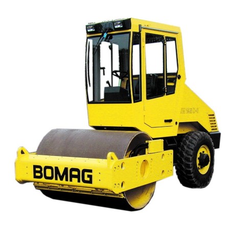
BOMAG BW145 D-3 / DH-3 / PDH-3 Operation & Maintenance Manual
This technical collection covers the workshop, operation, maintenance or parts information documented in the index below. It does not promise a separate wiring-diagram collection.
Indexed subjects: Working on the engine; Working on hydraulic lines; 4.7 OPERATING THE PARKING BRAKE, STOPPING THE MACHINE.
Documentation scope: Documentation also references BW145 D-3 and PDH-3 variants with multiple serial-number groups; refer to the applicable machine specification.
Original technical index
- CONTENTS:
- BW 145 D-3 / DH-3 / PDH-3
- - S/N 101 581 21.... 901 581 47 ....
- - S/N 101 581 22.... 901 581 48 ....
- - S/N 101 581 23 .... 901 581 49 ....
- SINGLE DRUM ROLLER
- - BOMAG machines are products from the wide range of BOMAG compaction equipment.
- - BOMAG's vast experience, together with the most up-to-date production and testing methods, includ...
- -- These instructions comprise:
- -- Using these instructions will
- -- Compliance with the maintenance instructions will
- -- BOMAG shall not assume liability for safe functioning of the machine
- -- No warranty claims can be lodged for damage resulting from
- - Please note!
- - For your own safety you should only use BOMAG-spare parts.
- - We reserve the right for technical modifications without prior notification.
- - Please fill in
- -- Fig. 1
- -- Fig. 2
- -- Fig. 3
- -- 1 Technical Data
- -- Fig. 4
- - BW 145 D-3
- - BW 145 DH-3
- - BW 145 PDH-3
- - BW 145 D-3
- - BW 145 DH-3
- - BW 145 PDH-3
- - Weights
- - Travel characteristics
- - Drive
- - Brakes
- - Steering
- - Vibration
- - Tires
- - Tank contents
- - The following noise and vibration values according-the EC-directive for machines, edition (91/...
- - During operation these values may vary because of the existing operating conditions.
- - Noise value
- -- sound pressure level at the work place of the operator (with cabin):
- -- sound capacity level:
- - Vibration value
- -- Vibration of the entire boy (driver’s seat)
- -- Hand-arm vibration values
- -- 2 Safety regulations
- - General
- -- This BOMAG machine is built in accordance with the latest technical standard and the valid techni...
- -- Each person involved in operation, maintenance and repair of the machine must therefore read and ...
- - Intended use
- - Unintended use
- - Who is allowed-work with the machine?
- - Conversions and alterations-the machine
- - Safety notes in the operating and maintenance instructions:
- - Information and safety stickers/decals on the machine
- - Loading the machine
- - Towing the machine
- - Checking the roll-over protection structure (ROPS)
- - Starting the machine
- -- Before starting
- -- Starting
- -- Starting with jump leads
- -- Starting in closed rooms
- - Driving the machine
- -- Persons in the danger area
- -- Driving
- -- Driving on gradients and slopes
- -- Behaviour in traffic
- -- Check the effect of vibration
- - Parking the machine
- -- Parking on gradients or slopes
- - Filling the fuel tank
- -- Fire protection measures
- - Maintenance work
- -- Working on hydraulic lines
- -- Changing of hydraulic hoses
- -- Working on the engine
- -- Working in the electric system
- -- Working on the battery
- -- Working on the fuel system
- -- Working on wheels and tires
- -- Cleaning
- -- After maintenance work
- - Repair
- -- Test
- -- 3 Indicators and Controls
- -- Fig. 5
- 3.1 GENERAL NOTES
- - Fig. 6
- -- No. 1 = Multi-function display
- - The control and warning lamps light up while the engine is running:
- -- Fig. 7
- -- No. 2 = Rotary switch for flashing beacon
- -- Fig. 8
- -- No. 3 = Rotary switch, lighting (StVZO)
- -- Fig. 9
- -- No. 4 = Rotary switch for hazard light system
- -- Fig. 10
- -- No. 5 = Rotary switch for direction indicators left / right
- -- Fig. 11
- -- No. 6 = Rotary switch working lights
- -- Fig. 12
- -- No. 7 = Rotary switch, vibration
- -- Fig. 13
- -- No. 8 = Rotary switch for speed range selection
- -- Fig. 14
- -- No. 9 = Push button for warning horn
- -- Fig. 15
- -- No. 10 = Emergency stop switch
- -- Fig. 16
- -- No. 11 = Ignition switch
- -- Fig. 17
- -- No. 12 = Push button for vibration
- -- Fig. 18
- -- No. 13 = Travel lever
- -- Fig. 19
- -- No. 14 = Throttle lever
- -- No. 15 = Locking plate for throttle lever
- -- Fig. 20
- -- No. 16 = Fuses in electric installation box
- -- Fig. 21
- -- No. 17 = Main fuse for battery
- -- Fig. 22
- -- No. 18 = Pedal for dozer blade
- -- Fig. 23
- -- No. 19 = Fuse box, cabin
- -- No. 20 = Toggle switch, heating blower
- -- No. 21 = Toggle switch, flashing beacon
- -- No. 22 = Toggle switch, windscreen wiper/ washer, front
- -- No. 23 = Toggle switch, windscreen wiper/ washer, rear
- -- No. 24 = Cabin light
- -- No. 25 = Vent for fresh air intake
- -- Fig. 24
- -- No. 26 = Shut-off valve for cabin heater
- -- 4 Operation
- 4.1 GENERAL NOTES
- 4.2 TESTS BEFORE TAKING INTO OPERATION
- - Check:
- 4.3 STARTING THE ENGINE
- - Fig. 25
- - Fig. 26
- - Fig. 27
- - Fig. 28
- - Fig. 29
- - Fig. 30
- - Fig. 31
- - Fig. 32
- - Fig. 33
- 4.4 STARTING WITH JUMP LEADS
- - Fig. 34
- 4.5 DRIVING THE MACHINE
- - Fig. 35
- - Fig. 36
- - Fig. 37
- - Important notes on travel operation
- 4.6 EMERGENCY EXIT
- 4.7 OPERATING THE PARKING BRAKE, STOPPING THE MACHINE
- - Fig. 38
- 4.8 SHUTTING THE ENGINE DOWN
- - Fig. 39
- - Fig. 40
- - Fig. 41
- 4.9 SWITCHING THE VIBRATION ON AND OFF
- - Preselecting the vibration
- -- Fig. 42
- - Switching the vibration on
- -- Fig. 43
- -- Fig. 44
- - Switching the vibration off
- 4.10 ADJUSTING THE SEAT
- - Fig. 45
- 4.11 OPERATING THE HOOD
- - Fig. 46
- - Fig. 47
- 4.12 TOWING IN CASE OF AN ENGINE FAILURE
- - Fig. 48
- - Fig. 49
- - Fig. 50
- - After towing
- -- Fig. 51
- -- Fig. 52
- 4.13 TRANSPORT
- - Fig. 53
- - Fig. 54
- - Fig. 55
- - Weights: See technical data
- -- 5 Maintenance
- 5.1 GENERAL NOTES ON MAINTENANCE
- - Notes on the fuel system
- - Notes on the performance of the engine
- - Notes on the hydraulic system
- 5.2 FUELS AND LUBRICANTS
- - Engine oil
- -- Quality
- -- Approved engine oils
- -- Oil viscosity
- -- Fig. 56
- -- Oil change intervals
- -- ACEA
- -- API
- - Fuels
- -- Quality
- -- Winter fuel
- -- Operation with rape seed oil methyl ester (RME „Bio Diesel“)
- - Hydraulic oil
- -- Bio-degradable hydraulic oil
- - Oil for drive axle
- - Lubrication grease
- 5.3 TABLE OF FUELS AND LUBRICANTS
- - Assembly
- - Fuel or lubricant
- - Quantity approx.
- - Summer
- - Winter
- 5.4 RUNNING-IN INSTRUCTIONS
- - The following maintenance work must be performed when running in new machines or overhauled engines:
- - After 50 operating hours
- - After 500 operating hours
- 5.5 MAINTENANCE CHART
- - With all maintenance intervals perform also the work for shorter preceding service intervals.
- - No.
- - Designation
- - Note
- - Every 10 operating hours
- - Every 250 operating hours
- - Every 500 operating hours
- - Every 1000 operating hours
- - Every 2000 operating hours
- - Every 3000 operating hours
- - Every 5000 operating hours
- - As required
- 5.6 CHECKING THE ENGINE OIL LEVEL
- - Fig. 57
- - For quality and quantity of oil refer-the table of fuels and lubricants
- 5.7 CHECKING THE FUEL FILTER WATER SEPARATOR
- - Fig. 58
- 5.8 CHECKING THE FUEL LEVEL
- - Fig. 59
- - Fig. 60
- - For quality of fuel refer-the table of fuels and lubricants.
- 5.9 CHECKING THE HYDRAULIC OIL LEVEL
- - Fig. 61
- - Normal level
- - Minimum level
- -- Fig. 62
- - For quality and quantity of oil refer-the table of fuels and lubricants.
- 5.10 CHECKING THE TIRE PRESSURE
- - Fig. 63
- - Nominal value see "technical data".
- 5.11 CLEANING THE COOLING FINS ON THE RADIATOR
- - Cleaning with compressed air
- -- Fig. 64
- - Cleaning with cold cleansing agent
- 5.12 CLEANING THE COOLING FINS ON THE HYDRAULIC OIL COOLER
- - Cleaning with compressed air
- -- Fig. 65
- - Cleaning with cold cleansing agent
- 5.13 CHECK THE OIL LEVEL IN THE DRIVE AXLE
- - Fig. 66
- - For quality of oil refer-the table of fuels and lubricants.
- 5.14 CHECKING THE OIL LEVEL IN LEFT/ RIGHT WHEEL HUBS
- - Fig. 67
- - For quality of oil refer-the table of fuels and lubricants.
- 5.15 CHECKING THE OIL LEVEL IN THE VIBRATION BEARINGS
- - Fig. 68
- - For quality of oil refer-the table of fuels and lubricants.
- 5.16 SERVICING THE BATTERY
- - Fig. 69
- - Fig. 70
- 5.17 DRAINING THE SLUDGE FROM THE FUEL TANK
- - Fig. 71
- 5.18 CHANGE ENGINE OIL AND OIL FILTER CARTRIDGE
- - Fig. 72
- - Fig. 73
- - Fig. 74
- - For quality and quantity of oil refer-the table of fuels and lubricants.
- -- Fig. 75
- -- Fig. 76
- 5.19 CHECKING THE V-BELT TENSION, TIGHTENING
- - Checking the V-belt
- -- Fig. 77
- - Retightening the V-belt
- -- Fig. 78
- 5.20 CHECKING, ADJUSTING THE VALVE CLEARANCE
- - Valve clearance
- -- Fig. 79
- -- Fig. 80
- -- Fig. 81
- -- Fig. 82
- - Adjusting the valve clearance
- -- Fig. 83
- 5.21 CHANGING THE OIL IN THE VIBRATION BEARINGS
- - Fig. 84
- - Fig. 85
- - For quality and quantity of oil refer-the table of fuels and lubricants.
- 5.22 CHANGE THE OIL IN THE DRIVE AXLE
- - Fig. 86
- - Fig. 87
- - For quality and quantity of oil refer-the table of fuels and lubricants.
- 5.23 CHANGE THE OIL IN THE WHEEL HUBS
- - Fig. 88
- - Fig. 89
- - For quality and quantity of oil refer-the table of fuels and lubricants.
- 5.24 CHANGING THE FUEL PRE-FILTER
- - Fig. 90
- 5.25 CHANGING THE FUEL FILTER CARTRIDGE
- - Fig. 91
- 5.26 CHECKING THE FASTENINGS ON THE DIESEL ENGINE
- - Fig. 92
- - Fig. 93
- 5.27 TIGHTENING THE FASTENING OF THE AXLE ON THE FRAME
- - Fig. 94
- 5.28 TIGHTENING THE WHEEL NUTS
- - Fig. 95
- - Tightening torques 550 Nm (405 ft-lb) (M22x1,5)
- 5.29 CHECKING THE ROPS
- - Fig. 96
- 5.30 CHANGING HYDRAULIC OIL AND BREATHER FILTER
- - Fig. 97
- - Fig. 98
- - Nominal value:
- - For quality and quantity of oil refer-the table of fuels and lubricants.
- 5.31 CHANGING THE HYDRAULIC OIL FILTER
- - Fig. 99
- 5.32 CHECKING THE INJECTION VALVES
- 5.33 REPLACING THE TOOTHED BELT
- - Fig. 100
- 5.34 CHECKING, CLEANING, CHANGING THE COMBUSTION AIR FILTER
- - Fig. 101
- - Fig. 102
- - Fig. 103
- - Fig. 104
- - Fig. 105
- - Fig. 106
- - Fig. 107
- - Dry cleaning of the main filter element
- -- Fig. 108
- - Changing the safety filter element
- -- Fig. 109
- 5.35 ADJUSTING THE PARKING BRAKE
- - Fig. 110
- - Fig. 111
- - Fig. 112
- 5.36 CHANGING THE TIRES
- - Fig. 113
- 5.37 ADJUSTING THE SCRAPERS
- - smooth drum only
- -- Fig. 114
- - padfoot drum only
- -- Fig. 115
- 5.38 CHANGING THE FRESH AIR FILTER IN THE CABIN
- - Fig. 116
- 5.39 TIGHTENING TORQUES
- - Fig. 117
- 5.40 ENGINE CONSERVATION
- - Anti-corrosion oils are those that comply with the specification MIL-L-21260 B or TL 9150- 037/2 ...
- - A machine with a conserved engine must be marked by attaching a clearly visible warning tag.
- -- 6 Trouble shooting
- 6.1 GENERAL NOTES
- - The following work must only be carried out by qualified and trained personnel or by the sales se...
- - Please observe strictly the safety regulations in chapter 2 of these operating and maintenance in...
- 6.2 ENGINE
- - Faults
- - Possible cause
- - Remedy