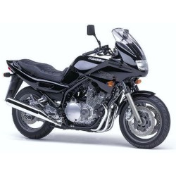
Yamaha FZR600 W WC - Service Repair Manual - Wiring Diagrams
Digital technical documentation with sections on Chapter 1., Motorcycle identification 1-1, Vehicle identification number . 1-1. Review the complete contents below for the systems and procedures covered.
Manual contents
- - Chapter 1.
- - General information
- - Motorcycle identification 1-1
- - Vehicle identification number . 1-1
- - Engine serial number . 1-1
- - Important information 1-2
- - Preparation for removal 1-2
- - All replacement parts . 1-2
- - Gasket, oil seals, and 0-rings 1-2
- - Lock washer/plates and cotter pins 1-3
- - Bearings and oil seals . 1-3
- - Cl rc lips . 1-3
- - Special tools 1-4
- - For tune up . 1-4
- - For engine service . 1-5
- - For chassis service . 1-8
- - For electrical components 1-8
- - Chapter 2.
- - Specifications
- - Specifications 2-1
- - General specifications 2-1
- - Maintenance specifications . 2-4
- - Engine. 2-4
- - Chassis 2-12
- - Electrical 2-15
- - General torque specifications 2-18
- - Definition of units 2-18
- - Lubrication point and grade of lubricant 2-19
- - Engine 2-19
- - Chassis 2-20
- - Lubrication diagram . 2-21
- - Coolant diagram . 2-22
- - Cable routing 2-23
- - Chapter 3.
- - Periodic inspection and adjustment
- - Introduction . 3-1
- - Maintenance interval chart 3-1
- - General maintenance/lubrication 3-2
- - Cowlings/covers removal and installation 3-4
- - Removal . 3-4
- - Installation . 3-6
- - Engine . 3-8
- - Exup cable adjustment (for california only) 3-8
- - Valve clearance adjustment . 3-9
- - Carburetor synchronization . 3-16
- - Idle speed adjustment 3-18
- - Throttle cable free play adjustment . 3-19
- - Spafik plug inspection . 3-20
- - Ignition timing check . 3-21
- - Compression pressure measurement . 3-22
- - Engine oil level inspection . 3-24
- - Engine 01 l replacement . 3-24
- - Engine oil filter replacement . 3-25
- - Clutch adjustment 3-27
- - Air filter cleaning . 3-28
- - Carburetor joint inspection 3-29
- - Fuel line inspection . 3-29
- - Crankcase ventilation hose inspection 3-29
- - Exhaust system inspection 3-30
- - Coolant level inspection . 3-30
- - Coolant replacement . 3-31
- - Chassis 3-34
- - Front brake adjustment 3-34
- - Rear brake adjustment . 3-34
- - Brake fluid inspection 3-35
- - Brake pad inspection 3-36
- - Brake light switch adjustment 3-36
- - Brake hose inspection . 3-37
- - Al r bleeding . 3-37
- - Dr ive chain slack adjustment 3-38
- - Drive chain lubrication 3-40
- - Change pedal adjustment 3-40
- - Front fork inspection 3-41
- - Steering head inspection . 3-41
- - Rear shock absorber adjustment 3-44
- - Tl re inspection 3-45
- - Wheel inspection 3-46
- - Cable inspection . 3-47
- - Lubrication 3-47
- - Electrical 3-49
- - Battery inspection 3-49
- - Fuse inspection 3-51
- - Headlight beam adjustment 3-53
- - Headlight bulb replacement . 3-53
- - Tail/brake bulb replacement 3-55
- - Chapter 4.
- - Engine overhaul
- - Engine removal . 4-1
- - Side cowlings and top cover. . 4-1
- - Fuel tank . 4-1
- - Engine oil 4-1
- - Coo lant . 4-1
- - Air fil tea case and carburetor 4-1
- - Radiator . 4-2
- - Muffler assembly 4-2
- - Clutch cable and drive chain 4-3
- - Leads . 4-4
- - Engine removal 4-5
- - Engine disassembly 4-7
- - Cylinder head cover, camshaft and
- - Cylinder head . 4-7
- - Cylinder and piston 4-10
- - Starter clutch . 4-12
- - Clutch 4-13
- - Starter motor and a.c. Generator . 4-14
- - Oil pan and 01 l strainer 4-15
- - Oil pump and shift shaft 4-16
- - Water pump . 4-17
- - Crankcase disassembly . 4-17
- - Transmission, shifter and shift cam 4-18
- - Crankshaft . 4-19
- - Valve pad and valve . 4-20
- - Connecting rod . 4-22
- - Inner rotor (oil pump) 4-22
- - Inspection and repair . 4-23
- - Cylinder head 4-23
- - Valve and valve guide . 4-24
- - Valve seat . • 4-26
- - Valve spring 4-29
- - Valve lifter . ••. 4-30
- - Camshaft, timing chain and cam sprocket . 4-30
- - Cylinder and piston . 4-32
- - Piston ring and piston pin . 4-34
- - Piston pin 4-35
- - Crankshaft and connecting rod 4-36
- - Oil pump 4-40
- - Primary drive . 4-41
- - Starter drives 4-42
- - Clutch . 4-43
- - Transmission 4-45
- - Shift shaft and stopper lever. 4-46
- - Oil jet nozzle . 4-47
- - Relief valve and pipe 4-47
- - Crankcase . 4-47
- - Bearing and oil seal 4-48
- - Exup valve and cables (fzr600wc only) 4-48
- - Engine assembly and adjustment . 4-49
- - Inner rotor (oil pump) . 4-49
- - Connecting rod 4-49
- - Valve pad and valve 4-50
- - Crankshaft 4-53
- - Transmission, shifter and shift cam . 4-56
- - Crankcase assembly . 4-57
- - Water pump 4-60
- - Shift shaft and oil pump . 4-60
- - Oil pan and oil strainer . 4-61
- - A.c. Magneto and starter motor 4-62
- - Clutch . 4-64
- - Starter clutch 4-67
- - Piston and cylinder . 4-70
- - Cylinder head and camshaft 4-74
- - Timing chain tensioner 4-79
- - Remounting engine 4-80
- - Chapter 5.
- - Cooling system
- - Radiator 5-1
- - Removal 5-2
- - Inspection 5-3
- - Installation . 5-4
- - Thermostatic valve . 5-6
- - Removal 5-6
- - Inspection 5-7
- - Installation . 5-7
- - Water pump . 5-8
- - Removal 5-8
- - Inspection 5-9
- - Installation . 5-9
- - Chapter 6.
- - Carburetor
- - Carburetor . 6-1
- - Section view 6-2
- - Removal . 6-3
- - Disassembly 6-4
- - Inspection 6-7
- - Assembly . 6-9
- - Installation . 6-11
- - Adjustment 6-13
- - Air injection (for california) 6-14
- - Air injection (al r induction system) 6-14
- - Air cut valve . 6-14
- - Air induction system inspection 6-15
- - Chapter 7.
- - Chassis
- - Front wheel 7-1
- - Removal . 7-2
- - Inspection 7-2
- - Installation . 7-4
- - Static wheel balance adjustment . 7-5
- - Rear wheel 7-7
- - Removal . 7-8
- - Inspection 7-8
- - Installation . 7-9
- - Static wheel balance adjustment . 7-9
- - Front and rear brake 7-10
- - Brake pad replacement 7-12
- - Caliper disassembly 7-16
- - Master cylinder disassembly 7-19
- - Inspection and repair 7-20
- - Assembly . 7-24
- - Front fork 7-31
- - Removal . 7-32
- - Disassembly 7-33
- - Inspection 7-34
- - Assembly . 7-35
- - Installation . 7-37
- - Steering head and handlebar 7-39
- - Removal . 7-41
- - Inspection 7-44
- - Installation . 7-45
- - Rear shock absorber and swingarm 7-50
- - Handling notes 7-52
- - Disposal notes . 7-52
- - Removal . 7-52
- - Inspection 7-56
- - Installation . 7-57
- - Drive chain and sprocket . 7-60
- - Removal . 7-60
- - Inspection and cleaning . 7-60
- - Installation . 7-62
- - Chapter 8.
- - Electrical
- - Fzr600w/wc circuit diagram . 8-1
- - Color code . 8-2
- - Electrical components . 8-3
- - Checking of switches 8-5
- - Switch connection as shown in manual 8-5
- - Checking switch for terminal connection . 8-5
- - Checking of bulbs (for headlight, tail/brake light,
- - Flasher light, meter light, etc.) . 8-8
- - Kinds of bulbs 8-8
- - Checking bulb condition . 8-8
- - Ignition system . 8-11
- - Circuit diagram 8-11
- - Digital ignition control system . 8-13
- - Troubleshooting . 8-14
- - Electrical starting system . 8-21
- - Circuit diagram 8-21
- - Starting circuit operation 8-23
- - Troubleshooting . 8-24
- - Starter motor . 8-30
- - Charging system . 8-33
- - Circuit diagram 8-33
- - Troubleshooting . 8-35
- - Lighting system •8-39
- - Circuit diagram . -8-39
- - Troubleshooting 8-41
- - Lighting system check . 8-44
- - Signal system . 8-50
- - Circuit diagram 8-50
- - Troubleshooting 8-51
- - Signal system check . 8-53
- - Cooling system 8-63
- - Circuit diagram 8-63
- - Troubleshooting 8-65
- - Fuel pump system 8-73
- - Circuit diagram 8-73
- - Fuel pump circuit operation . 8-75
- - Troubleshooting 8-76
- - Fuel pump test . 8-80
- - Exup system (for carifornia only) 8-81
- - Circuit diagram 8-81
- - Troubleshooting . 8-83
- - Chapter 9.
- - Troubleshooting
- - Starting failure/hard starting 9-1
- - Fuel system 9-1
- - Electrical system . 9-2
- - Compression system 9-2
- - Poor idle speed performance . 9-3
- - Poor idle speed performance 9-3
- - Poor medium and high speed performance 9-4
- - Poor medium and high speed performance . 9-4
- - Faul ty gear shifting . 9-4
- - Hard shifting 9-4
- - Shift pedal does not move . 9-4
- - Jump-out gear • • • • • . 9-4
- - Clutch slipping/dragging . 9-5
- - Clutch slipping . 9-5
- - Clutch dragging . 9-5
- - Overheating or over-cooling 9-6
- - Overheating . 9-6
- - Over-cooling . 9-6
- - Faul ty brake . 9-7
- - Poor braking effect . 9-7
- - Front fork oil leakage/malfunction 9-7
- - 01 l leakage 9-7
- - Malfunction . 9-7
- - Instable handling 9-8
- - Handlebars 9-8
- - Steering . 9-8
- - Front forks 9-8
- - Wheels . 9-8
- - Frame 9-8
- - Rear arm . 9-8
- - Rear cushion . 9-8
- - Drive chain 9-8
- - Fairing . 9-8
- - Faul ty signals and lights 9-9
- - Headlight dark 9-9
- - Bulb burnt out . 9-9
- - Flasher does not light 9-9
- - Flasher keeps on . 9-9
- - Flasher winks slower 9-10
- - Flasher winks quicker . 9-10
- - Horn is inoperative 9-10
- - Fzr600 w/wc wiring diagram