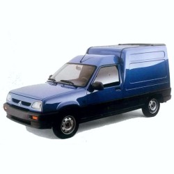
- -$10.00


A courier drops off a 2004 model. You turn the key, nothing happens, and that dreaded immobilizer light just flashes aggressively. A rookie might immediately suspect the Engine Speed Sensor (273) or simply toss a new programmed key at the ignition. In practical diagnostics, the true culprit on these French utility vans is frequently a degraded harness connection between the Transponder Unit (957) and the Passenger Compartment Computer (645).
If the UCH doesn't read the key code cleanly, it completely denies the unlock signal to the Injection Computer (120). By leveraging this factory-level schematic, you trace the exact voltage path from the source. You can verify the 12V supply to the transponder ring and perform precise voltage drop testing on the specific return signal wire before condemning a heavily priced immobilizer module.
During its lifespan, Renault offered incredibly varied powertrains for this light commercial vehicle. You simply cannot use standard petrol schematics to troubleshoot the factory gas models.
This interactive HTML-based workshop reference provides dedicated circuitry for the alternative fuel systems. If the van won't switch over from petrol, you can directly map the LPG Computer (997) to the LPG Solenoid Valve on Tank (1002) and the LPG or Petrol Selector Switch (1003).
For the diesel variants, pinpointing a hard-start in cold weather is simplified by tracing the Preheating Unit (257) down to the individual Preheater Plugs (680-683). You get the specific pinout reference guide necessary to back-probe the harness safely, avoiding any accidental shorts across the 5V sensor reference lines.
A massive headache on these aging vans involves shared ground paths. When activating the left turn signal causes the radio to reset, you have a floating ground searching for a new path.
Instead of ripping out the entire dashboard, pull up the Earth section within the electrical system diagrams. The layout identifies physical connection points like the Left-Hand A-Pillar Electrical Earth (MK) or the main Engine Electrical Earth (NF). Verifying these specific anchor points ensures your Kangoo I parasitic draw diagnosis is built on a solid foundation, eliminating hours of blind wire chasing through the chassis.
Forget about scrolling endlessly through a thousand-page flat PDF. This 397 MB file is built as an interactive HTML interface compressed into a standard ZIP folder.
Once extracted on your Toughbook or shop PC, you simply open the master index in your web browser. This dynamic structure allows you to click directly on component numbers—jumping straight from the Diagnostic Socket (225) to the Anti-Lock Braking System Computer (118). It is a vastly superior format for quick, dirty shop-floor navigation when your hands are full.
A broken work van costs your fleet accounts money every single minute it sits on the lift. We built our data retrieval system to keep your bays turning without delay.
Get instant access wiring diagrams and eliminate guesswork in your daily repairs.
What is the best way to trace an intermittent signal drop from the TDC sensor on the 1.5 dCi engine?
The documentation provides a dedicated circuit map for the TDC Sensor (149) routing directly to the Injection Computer. You can pinpoint the specific Engine/Injection Connection (R37) to check for terminal fretting or moisture intrusion, a notoriously common fault on these powertrains.
Why would the rear wiper and the heated screen fail simultaneously after loading heavy cargo?
These components often share ground distribution points at the rear of the body, which can be damaged by shifting freight. By checking the Rear Screen De-Icing (200) and Rear Screen Wiper Motor (211) schematics, you can cross-reference their ground paths to the Rear Left-Hand Electrical Earth (MG) to find the rusted or severed chassis eyelet.
How do I open the HTML diagrams once the ZIP file is downloaded?
When you download wiring diagrams instantly, you receive a compressed ZIP folder. Right-click the folder and select "Extract All" to a local directory on your PC. Then, double-click the master "index.html" file to open it in Chrome, Edge, or Safari, enabling the fully clickable schematic menus.