• -$10.00
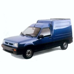
Renault Kangoo II Electrical Wiring Diagrams 2007-2010
search
  • Renault Kangoo II Electrical Wiring Diagrams 2007-2010
  • Renault Kangoo II Electrical Wiring Diagrams 2007-2010

Renault Kangoo II Electrical Wiring Diagrams 2007-2010

$29.95
$19.95 Save $10.00
No tax

Quantity

YOUTUBE Official Channel @SoloPDFcom (+18,000 subs). Trusted by mechanics worldwide using professional workshop manuals and wiring diagrams.

2007-2010 Index

Power Distribution, Starting & Charging

  • Wiring diagrams and component locators covering the battery, alternator, starter motor, cigarette lighter, starting switch, passenger compartment and engine fuse boxes, and power supply fuse boards.
  • Schematics for switching protection units, power relays, window closer control relays, accessories relays, and additional preheater plug relay units.

Engine Management & Fuel Injection Systems

  • Circuit diagrams for injection computers, injectors 1 through 5, preheater plugs, cylinder sensors, TDC sensors, manifold and rail pressure sensors, water-in-diesel sensors, and fuel temperature sensors.
  • Wiring and locations for motorized throttle bodies, pencil ignition coils 1 to 4, air flow meters, fuel pumps, fuel rail pressure regulators, motorized EGR solenoid valves, and turbocharger control/pressure sensors.

Transmission, ABS/ESP & Steering Electronics

  • Wiring diagrams for gear selector switches, reversing lights switches, manual gearbox neutral sensors, anti-lock braking system (ABS), and electronic stability program (ESP) computers.
  • Schematics covering wheel speed sensors, ESP transverse and lateral acceleration sensors, handbrake and brake switches, brake fluid level sensors, and variable power-assisted steering systems.

Body Control, Access, Windows & Security Systems

  • Circuit diagrams for passenger compartment computers, central locking, swing and side door electric locking, tailgate locks, fuel filler flap motors, and electric window controls and motors.
  • Schematics for electric rear-view mirrors, heated seat controls, sunroof controls, alarm computers, and ultrasonic intrusion sensors.

Airbag & Safety Restraint Systems

  • Wiring diagrams for airbag and pretensioner computers, driver and passenger frontal airbags, side curtain airbags, and front pelvic/chest side airbags.
  • Locators and schematics for front side impact sensors (satellites), front buckle pretensioners, seat belt switches, seat belt warning modules, and passenger airbag disabling keys.

Climate Control, Heating & Ventilation (HVAC)

  • Wiring schematics for air conditioning control units and panels, AC clutches, low-speed fan resistance, cooling fan units, fan output modules, and coolant gas pressure sensors.
  • Diagrams for mixing flaps, recycling motors, blown air temperature sensors, passenger compartment fan assemblies, and additional passenger compartment heating relays and plugs.

Lighting, Instrumentation & Wiping Systems

  • Circuit locators for right and left headlights, headlight corrector motors, front and rear fog lights, tail lights, registration plate lights, third brake lights, and interior courtesy and luggage lighting.
  • Schematics for instrument panels, clocks, external temperature and carphone displays, windscreen and rear screen wiper and washer motors, bi-directional washer pumps, and parking aid computers with detection sensors and buzzers.

Infotainment, Audio & Communication Systems

  • Wiring diagrams for radios, front and rear speakers, front and rear door speakers, tweeters, aerial amplifiers, and radio aerial connections.
  • Schematics for hands-free mobile phone microphones, video displays, multimedia connection points, second row accessories inputs, and steering wheel warning controls.

Wiring Harness Connectors & Ground Distribution Index

  • Detailed wiring connector routing schematics linking dashboard harnesses to doors, engine compartments, tailgates, front bumpers, seats, and multimedia systems via R-series connection points.
  • Comprehensive electrical earth and ground distribution mapping for engine, body, ABS, PTC, console, and cross-member grounding points utilizing M-series, N-series, MW, and NL earth designations.

The Commercial Door Harness Failure

Let's dissect a notoriously common workshop headache on this French commercial platform. A customer drops off a Kangoo II where the Rear Right Door Electric Locking (138) and the Swing Door Electric Locking (71) have completely failed, triggering a constant "door open" warning on the Instrument Panel (247). A green apprentice might rip the door latches out immediately. In practical diagnostics, the root cause is usually wire fatigue in the umbilical boot between the body and the rear doors, or a burnt pin at the Passenger Compartment Computer (645).

By leveraging this interactive HTML resource, you can trace the exact voltage path from the UCH down through the Left Rear / Left-Hand Tailgate Connection (R15). You identify the exact wire tracer color and pin number, test continuity across the hinge boot, and fix the broken wire without wasting hours dismantling the cargo area.

Managing the Multiplex Network & UCH

Between 2007 and 2010, the Kangoo II transitioned into a heavily multiplexed architecture. You simply cannot troubleshoot cabin faults by probing randomly with a test light. The Passenger Compartment Computer (645) and the Multiplex Line Interface Unit (1714) act as the central nervous system.

If the vehicle is suffering from an overnight battery drain, this technical document allows you to map the specific output lines from the Passenger Compartment Fuse and Relay Boxes (260, 1531, 1619). You pull the correct fuses to see if the network goes to sleep, effectively isolating whether the drain is coming from the Radio (261), the Alarm Computer (427), or a stuck Electric Window Relay (703).

DPF and Diesel Injection Circuitry

European diesel models require exact sensor voltages to keep the emissions systems out of limp mode. When dealing with a blocked Particle Filter, you need to know if the sensors are actually receiving their 5-volt reference.

This reference guide provides dedicated schematics for the Injection Computer (120). You get precise terminal routing for the Particle Filter Upstream Temperature Sensor (1287), Downstream Sensor (1288), and Differential Pressure Sensor (1290). Verifying these sensor inputs at the ECU connector prevents the catastrophic mistake of replacing a healthy DPF unit due to a chafed harness rubbing against the exhaust shield.

The Critical Role of Earth Distribution

A massive percentage of electrical gremlins on the Kangoo II trace back to floating grounds. If the front wipers (212) activate when the cooling fan (188) kicks on, you have a shared ground seeking a new path.

This data set extensively catalogs the grounding grid. You can cross-reference physical anchor points like the Dashboard Left-Hand Cross Member Electrical Earth (NAM), the Tunnel Electrical Earth (NAP), or the primary Engine General Electrical Earth (MHA). By performing voltage drop tests at these specific studs, you resolve bizarre back-feed issues efficiently.

Interactive HTML Workshop Navigation

Unlike a flat, cumbersome PDF book, this 201 MB file is compiled as an interactive HTML web interface compressed within a ZIP file. Once extracted on your Toughbook, you open the index in your browser. Need to find the "DP0" Automatic Gearbox Module (971)? Click it in the index, and the wiring diagram loads instantly with clickable links to related splice blocks, diagnostic sockets (225), and ground points.

Shop-Floor Digital Fulfillment

We know you can't leave a vehicle stranded on the hoist waiting for postal delivery. Our digital deployment is engineered for immediate action.

  • Secure Funding: Checkout safely utilizing Apple Pay, Google Pay, PayPal, or any standard Credit Card.
  • Instant Handoff: The moment your transaction is authorized, your download link is dispatched to your email and permanently logged into your secure customer account.
  • Flexible Access Window: Your specific URL remains active for 10 days, supporting up to 10 separate downloads. This ensures you can deploy the ZIP folder to your diagnostic cart, office PC, and mobile device.
  • Data Integrity Promise: Did the shop PC reboot mid-extraction? Did the ZIP file fail to open? Contact our team for an emergency backup delivery via a direct Dropbox pipeline.
  • HTML Setup Support: Unfamiliar with extracting ZIP files or using HTML manuals on a shop tablet? We built a 60-second video tutorial to get you running: https://servicemanuals.info/How-to-Download.mp4

Get immediate access to the full service manual and start diagnosing with precision.

Frequently Asked Questions

I'm diagnosing a hard shift on the DP0 automatic transmission. Are the solenoid circuits mapped clearly?
Yes. The index covers the "DP0" Automatic Gearbox Module (971) in extreme detail. You can trace the pathways for the Exchanger Flow Lock-up Solenoid Valve (1019) and the Gearbox Input Speed Sensor (1060), allowing you to verify transmission harness integrity before condemning the valve body.

We have a Kangoo II that won't start, and the scanner cannot ping the engine module. Does this provide the CAN lines for the diagnostic port?
Absolutely. You can track the multiplex communication lines directly from the Diagnostic Socket (225) through the Multiplex Line Interface Unit (1714) and out to the Injection Computer (120). This helps you locate broken twisted-pair wires causing the communication blackout.

How do I actually view the schematics if it's not a standard PDF file?
Because you download wiring diagram files in a ZIP-compressed HTML format, you must first right-click and "Extract All" to a folder on your computer. Inside that extracted folder, simply double-click the main "index.html" file. It will open in your default web browser (like Chrome or Firefox), presenting a fully clickable, interactive menu.

Can this help identify which specific fuse is keeping the passenger compartment computer awake during a parasitic draw test?
Definitely. By cross-referencing the Passenger Compartment Fuse and Relay Boxes (260, 1531, 1619) with the UCH (645) schematics, you can map the exact hot-at-all-times circuits. This prevents you from randomly pulling fuses and accidentally waking up other sleeping modules.