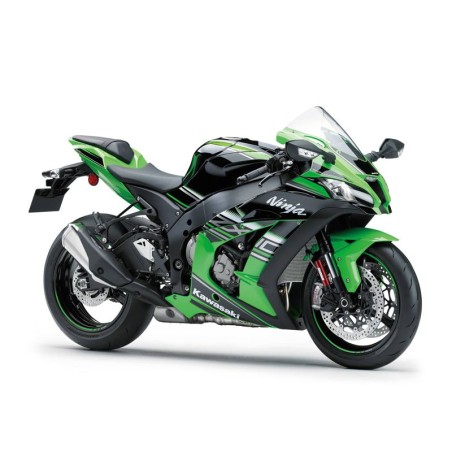
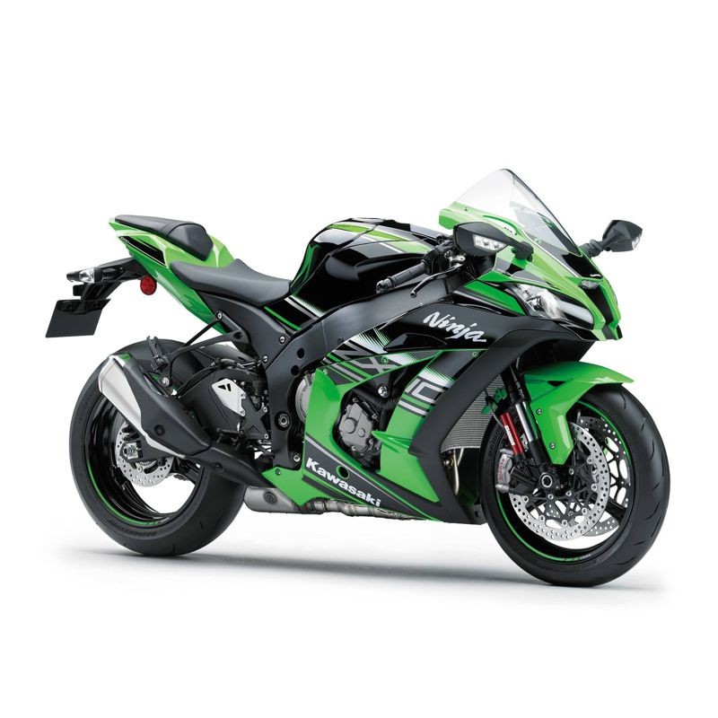
Kawasaki ZX-10R from 2016 — Service & Repair Manual with Wiring Diagrams
This download contains the workshop repair chapters and separately identifiable electrical diagrams for Kawasaki ZX-10R from 2016. The original technical index is reproduced below in full and in order. Indexed topics do not imply additional unlisted procedures.
Documentation language(s) stated in the original listing: English.
Selected original index topics: Engine Oil Flow Chart; Periodic Maintenance Chart; Before Servicing.
Original technical index
- GENERAL INFORMATION
- - Before Servicing
- - Model Identification
- - General Specifications
- - Unit Conversion Table
- PERIODIC MAINTENANCE
- - Periodic Maintenance Chart
- - Torque and Locking Agent
- - Specifications
- - Special Tools
- - Periodic Maintenance Procedures
- FUEL SYSTEM (DFI)
- - Exploded View
- - DFI System
- - DFI Parts Location
- - Specifications
- - Special Tools and Sealant
- - DFI Servicing Precautions
- - Troubleshooting the DFI System
- - DFI System Troubleshooting Guide
- - Warning Indicator Light (LED)
- - ECU
- - DFI Power Source
- - Fuel Line
- - Fuel Pump
- - Fuel Injectors
- - Throttle Grip and Cables
- - Throttle Body Assy
- - Nozzle Assy
- - Air Cleaner
- - Air Line
- - Fuel Tank
- - Evaporative Emission Control System (Other than US and CA Models)
- COOLING SYSTEM
- - Exploded View
- - Coolant Flow Chart
- - Specifications
- - Special Tools and Sealant
- - Coolant
- - Water Pump
- - Radiator
- - Thermostat
- - Hoses and Pipes
- - Water Temperature Sensor
- ENGINE TOP END
- - Exploded View
- - Exhaust System Identification
- - Specifications
- - Special Tools and Sealant
- - Clean Air System
- - Cylinder Head Cover
- - Camshaft Chain Tensioner
- - Camshaft, Camshaft Chain
- - Cylinder Head
- - Valves
- - Throttle Body Assy Holder
- - Muffler
- CLUTCH
- - Exploded View
- - Specifications
- - Special Tool and Sealant
- - Clutch Lever and Cable
- - Clutch Cover
- - Clutch
- ENGINE LUBRICATION SYSTEM
- - Exploded View
- - Engine Oil Flow Chart
- - Specifications
- - Special Tools and Sealant
- - Engine Oil and Oil Filter
- - Oil Pan
- - Oil Pressure Relief Valve
- - Oil Pump
- - Oil Cooler
- - Oil Pressure Measurement
- - Oil Pressure Switch
- ENGINE REMOVAL/INSTALLATION
- - Exploded View
- - Special Tool
- - Engine Removal/Installation
- CRANKSHAFT/TRANSMISSION
- - Exploded View
- - Specifications
- - Special Tools and Sealants
- - Crankcase
- - Crankshaft and Connecting Rods
- - Pistons
- - Balancer
- - Torque Limiter
- - Starter Motor Clutch
- - Transmission
- - External Shift Mechanism
- - Ball Bearing, Needle Bearing, and Oil Seal
- WHEELS/TIRES
- - Exploded View
- - Specifications
- - Special Tools
- - Wheels (Rims)
- - Tires
- - Hub Bearing
- FINAL DRIVE
- - Exploded View
- - Specifications
- - Special Tools
- - Drive Chain
- - Sprocket, Coupling
- BRAKES
- - Exploded View
- - Specifications
- - Special Tool
- - Brake Lever, Brake Pedal
- - Calipers
- - Brake Pads
- - Master Cylinder
- - Brake Disc
- - Brake Fluid
- - Brake Hose
- - Anti-lock Brake System (Equipped Models)
- SUSPENSION
- - Exploded View
- - Specifications
- - Special Tools
- - Front Fork
- - Rear Shock Absorber
- - Swingarm
- - Tie-Rod, Rocker Arm
- STEERING
- - Exploded View
- - Special Tools
- - Steering
- - Electronic Steering Damper (ESD)
- - Steering Stem
- - Handlebar
- FRAME
- - Exploded View
- - Seats
- - Fairings
- - Seat Covers
- - Fenders
- - Frame
- - Windshield
- - Guard
- - Rear View Mirrors
- - Side Stand
- ELECTRICAL SYSTEM
- - Exploded View
- - Specifications
- - Special Tools and Sealant
- - Parts Location
- - Wiring Diagram (ZX1000R without Immobilizer)
- - Wiring Diagram (ZX1000R with Immobilizer)
- - Wiring Diagram (ZX1000S without Immobilizer)
- - Wiring Diagram (ZX1000S with Immobilizer)
- - Precautions
- - Electrical Wiring
- - Battery
- - Charging System
- - Ignition System
- - Electric Starter System
- - Lighting System
- - Air Switching Valve
- - Air Intake Solenoid Valve
- - Radiator Fan System
- - Meter, Gauge, Indicator Unit
- - Immobilizer System (Equipped Models)
- - Switches and Sensors
- - Relay
- - Fuse
- SELF-DIAGNOSIS SYSTEM
- - Specifications
- - Special Tools
- - Self-Diagnosis
- - Throttle Position Sensor (Service Code 11) (DTC P0120, P0121, P0122, P0220, P0223)
- - Intake Air Pressure Sensor #1 (Service Code 12) (DTC P0105, P0107)
- - Intake Air Temperature Sensor (Service Code 13) (DTC P0110, P0112)
- - Water Temperature Sensor (Service Code 14) (DTC P0115, P0117)
- - Intake Air Pressure Sensor #2 (Service Code 16) (DTC P2226, P2227, P2228)
- - Accelerator Position Sensor (Service Code 18) (DTC P2120, P2121, P2123, P2125, P2128)
- - ABS Hydraulic Unit Communication Error (Service Code 1B, ZX1000S)
- - Crankshaft Sensor (Service Code 21) (DTC P0335)
- - Rear Wheel Rotation Sensor Signal (Service Code 24) (DTC P2158)
- - Gear Position Sensor (Service Code 25) (DTC P0914, P0917)
- - Front Wheel Rotation Sensor Signal (Service Code 27) (DTC P0500)
- - Air Intake Solenoid Valve (Service Code 2D) (DTC P0660)
- - Vehicle-down Sensor (Service Code 31) (DTC C0064)
- - Oxygen Sensor - not activated (Service Code 33) (DTC P0130, P0132)
- - Exhaust Butterfly Valve Actuator Sensor (Service Code 34) (DTC P048B, P048E)
- - Immobilizer Amplifier (Service Code 35, Equipped Models)
- - Blank Key Detection (Service Code 36, Equipped Models)
- - ECU Communication Error (Service Code 39) (DTC U0001)
- - Purge Valve (Service Code 3A, Other than US and CA Models) (DTC P0443)
- - ESD ECU Communication Error (Service Code 3C)
- - Quick Shifter Sensor (Service Code 3E) (DTC P0826)
- - Primary Fuel Injectors #1, #2, #3, #4 (Service Code 41, 42, 43, 44) (DTC P0201, P0202, P0203, P0204)
- - Fuel Pump Relay (Service Code 46) (DTC P0627)
- - Return Spring (Service Code 49) (DTC P2119)
- - Secondary Fuel Injectors #1, #2, #3, #4 (Service Code 4A, 4B, 4C, 4D) (DTC P0205, P0206, P0207, P0208)
- - Stick Coils #1, #2, #3, #4 (Service Code 51, 52, 53, 54) (DTC P0351, P0352, P0353, P0354)
- - Radiator Fan Relay (Service Code 56) (DTC P0480)
- - ETV Actuator (Service Code 58) (DTC P2100)
- - Exhaust Butterfly Valve Actuator (Service Code 63) (DTC P0475)
- - Air Switching Valve (Service Code 64) (DTC P0410)
- - Oxygen Sensor Heater (Service Code 67) (DTC P0030)
- - Fuel Supply System (Service Code 94) (DTC P0170)
- - Battery Voltage (Service Code 97) (DTC P0562)
- - ETV Control Circuit (Service Code 98) (DTC P0607)
- - ESD Actuator Error (Service Code E2E)
- - ESD ECU Error (Service Code E3B)
- - ESD Calibration Error (Service Code E3F)
- - IMU (Inertial Measurement Unit) (Service Code E8E)
- - IMU (Inertial Measurement Unit) Communication Error (Service Code E8F)
- - ABS Service Codes (ZX1000S)
- APPENDIX
- - Cable, Wire, and Hose Routing
- - Troubleshooting Guide