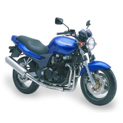
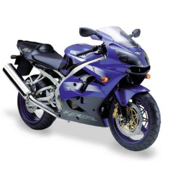
Kawasaki Ninja ZX-14 ZZR 1400 ABS (2006-11) - Repair, Service Manual, Wiring Diagrams and Owners Manual
Digital technical manual for the Kawasaki Ninja ZX-14 ZZR 1400 ABS (2006-11) - Repair, Service Manual, Wiring Diagrams and Owners Manual. Contents include SERVICE MANUAL (2006-2011), 1.General Information, - Before starting-perform an inspection service or carry out a. Browse the full section list below to review the systems and procedures covered.
Manual contents
- SERVICE MANUAL (2006-2011)
- 1.General Information
- - Before starting-perform an inspection service or carry out a
- - Battery Ground
- - Edges of Parts
- - Solvent
- - Cleaning vehicle before disassembly
- - Arrangement and Cleaning of Removed Parts
- - Storage of Removed Parts
- - Inspection
- - Replacement Parts
- - Assembly Order
- - Tightening Sequence
- - Tightening Torque
- - Force
- - Gasket, O-ring
- - Liquid Gasket, Non-permanent Locking Agent
- - Press
- - Ball Bearing and Needle Bearing
- - Oil Seal, Grease Seal
- - Circlips, Cotter Pins
- - Lubrication
- - Direction of Engine Rotation
- - Electrical Wires
- - Instrument
- - ZX1400A6F (Europe) Left Side View
- - ZX1400A6F (Europe) Right Side View
- - Frame Number
- - Engine Number
- - ZX1400A6F (United States and Canada) Left Side View
- - ZX1400A6F (United States and Canada) Right Side View
- - ZX1400A6F (Malaysia) Left Side View
- - ZX1400A6F (Malaysia) Right Side View
- - ZX1400B6F (Europe) Left Side View
- - ZX1400B6F (Europe) Right Side View
- - ZX1400B6F (Malaysia) Left Side View
- - ZX1400B6F (Malaysia) Right Side View
- - Overview
- - Structure and Function
- - System failure and maintenance
- - Prefixes for Units
- - Units of Temperature
- 2.Periodic Maintenance
- - The scheduled maintenance must be done in accordance with this c
- - The following tables list the tightening torque for the major fa
- - Inside Circlip Pliers:
- - Fuel System (DFI)
- - Throttle Control System Inspection
- - Engine Vacuum Synchronization Inspection
- - Idle Speed Inspection
- - Idle Speed Adjustment
- - Fuel Hose Inspection (fuel leak, damage, installation condition)
- - Cooling System
- - Evaporative Emission Control System (California Model)
- - Air Suction System
- - Engine Top End
- - Clutch and Drive Train
- - Wheels/Tires
- - Drive Train
- - Brake System
- - Suspensions
- - Steering System
- - Electrical System
- - Others
- - Replacement Parts
- 3.Fuel System (DFI)
- - DFI System
- - Terminal Numbers of ECU Connectors
- - Main Throttle Sensor [A]
- - Oil Pressure Gauge, 5 kgf/cm :
- - DFI Servicing Precautions
- - Torque -
- - Outline
- - Special Tool -
- - Sealant -
- - Special Tool -
- - DFI Diagnosis Flow Chart
- - Inquiries-Rider
- - NOTE
- - Self-diagnosis Outline
- - Self-diagnosis Procedures
- - Self-Diagnosis Flow Chart
- - Backups
- - The main throttle sensor is a rotating variable resistor that ch
- - Main Throttle Sensor Removal/Adjustment
- - Input Voltage Inspection
- - Output Voltage Inspection
- - Resistance Inspection
- - Main Throttle Sensor Circuit
- - CAUTION
- - Removal
- - Installation
- - Input Voltage Inspection
- - Output Voltage Inspection
- - Inlet Air Pressure Sensor Circuit
- - Removal/Installation
- - Output Voltage Inspection
- - Sensor Resistance Inspection
- - Inlet Air Temperature Sensor Circuit
- - Removal/Installation
- - Torque -
- - Output Voltage Inspection
- - Sensor Resistance Inspection
- - Water Temperature Sensor Circuit
- - CAUTION
- - Removal
- - Installation
- - Input Voltage Inspection
- - Output Voltage Inspection
- - Atmospheric Pressure Sensor Circuit
- - Atmospheric Pressure/Altitude Relationship
- - Crankshaft Sensor Removal/Installation
- - Crankshaft Sensor Inspection
- - Crankshaft Sensor Circuit
- - Camshaft Position Sensor Removal/Installation
- - Camshaft Position Sensor Inspection
- - Camshaft Position Sensor Circuit
- - Speed Sensor Removal/Installation
- - Speed Sensor Inspection
- - Input Voltage Inspection
- - Output Voltage Inspection
- - Gear Position Switch Removal/Installation
- - Gear Position Switch Inspection
- - Input Voltage Inspection
- - Gear Position Switch Circuit
- - This sensor has a weight [A] with two magnets inside, and sends
- - Removal
- - Installation
- - Inspection
- - Vehicle-down Sensor Circuit
- - The subthrottle sensor is a rotating variable resistor that chan
- - Subthrottle Sensor Removal/Adjustment
- - Input Voltage Inspection
- - Output Voltage Inspection
- - Resistance Inspection
- - Subthrottle Sensor Circuit
- - Antenna Resistance Inspection
- - Amplifier Input Voltage Inspection
- - User Key Inspection
- - Immobilizer System Circuit
- - Fuel Pump Relay Removal
- - Fuel Pump Relay Inspection
- - Fuel Pump Relay Circuit
- - Stick Coil ##1: Service Code 51
- - Removal/Installation
- - Input Voltage Inspection
- - Stick Coil Circuit
- - Subthrottle Valve Actuator Removal
- - Subthrottle Valve Actuator Inspection
- - Resistance Inspection
- - Input Voltage Inspection
- - Subthrottle Valve Actuator Circuit
- - ECU Main Relay Inspection
- - CAUTION
- - ECU Identification
- - ECU Removal
- - ECU Installation
- - ECU Power Supply Inspection
- - ECU Power Source Circuit
- - CAN Communication Line Circuit
- - ECU Fuse Removal
- - ECU Fuse Installation
- - ECU Fuse Inspection
- - Light (LED) Inspection
- - Warning Indicator Light (LED) Circuit
- - Fuel Pressure Inspection
- - Special Tools -
- - Fuel Flow Rate Inspection
- - Fuel Pump Removal
- - Fuel Pump Installation
- - Operation Inspection
- - Operating Voltage Inspection
- - Fuel Pump Circuit
- - Removal/Installation
- - Power Source Voltage Inspection
- - Output Voltage Inspection
- - Audible Inspection
- - Injector Signal Test
- - Injector Resistance Inspection
- - Injector Unit Test
- - Injector Fuel Line Inspection
- - Fuel Injector Circuit
- - Free Play Inspection
- - Free Play Adjustment
- - Cable Installation
- - Cable Lubrication
- - Idle Speed Inspection
- - Throttle Bore Cleaning
- - Synchronization Inspection
- - Synchronization Adjustment
- - Throttle Body Assy Removal
- - Throttle Body Assy Installation
- - Throttle Body Assy Disassembly
- - Element Removal
- - Element Installation
- - Air Cleaner Element Inspection
- - Air Cleaner Element Holder Removal
- - Air Cleaner Element Holder Installation
- - Oil Draining
- - Rear Air Inlet Duct Removal
- - Rear Air Inlet Duct Installation
- - Front and Middle Air Inlet Duct Removal
- - Front and Middle Air Inlet Duct Installation
- - Fuel Tank Removal
- - Fuel Tank Installation
- - Fuel Tank and Cap Inspection
- - Fuel Tank Cleaning
- - The Evaporative Emission Control System routes fuel vapors from
- - Parts Removal/Installation
- - Hose Inspection
- - Separator Inspection
- - Separator Operation Test
- - Canister Inspection
- 4.Cooling System
- - Coolant Deterioration Inspection
- - Coolant Level Inspection
- - Coolant Draining
- - Coolant Filling
- - Pressure Testing
- - Cooling System Flushing
- - Coolant Reserve Tank Removal/Installation
- - Water Pump Removal
- - Water Pump Installation
- - Water Pump Impeller Inspection
- - Radiator and Radiator Fan Removal
- - Radiator and Radiator Fan Installation
- - Radiator Inspection
- - Radiator Cap Inspection
- - Radiator Filler Neck Inspection
- - Thermostat Removal
- - Thermostat Installation
- - Thermostat Inspection
- - Hose Installation
- - Torque -
- - Hose Inspection
- - CAUTION
- - Water Temperature Sensor Removal
- - Water Temperature Sensor Inspection
- 5.Engine Top End
- - Compression Gauge, 20 kgf/cm :
- - Air Suction Valve Removal
- - Air Suction Valve Installation
- - Air Suction Valve Inspection
- - Air Switching Valve Removal
- - Air Switching Valve Installation
- - Air Switching Valve Operation Test
- - Air Switching Valve Unit Test
- - Clean Air System Hose Inspection
- - Cylinder Head Cover Removal
- - Cylinder Head Cover Installation
- - Camshaft Chain Tensioner Removal
- - Camshaft Chain Tensioner Installation
- - Camshaft Removal
- - Camshaft Installation
- - Camshaft, Camshaft Cap Wear
- - Camshaft Runout
- - Cam Wear
- - Camshaft Chain Removal
- - Camshaft Chain Installation
- - Cylinder Compression Measurement
- - Owner's Tool -
- - Special Tools -
- - Torque -
- - Cylinder Head Removal
- - Cylinder Head Installation
- - Cylinder Head Warp
- - Valve Clearance Inspection
- - Valve Removal
- - Valve Installation
- - Valve Guide Removal
- - Valve Guide Installation
- - Valve-to-Guide Clearance Measurement (Wobble Method)
- - Valve Seat Inspection
- - Valve Seat Repair
- - Throttle Body Holder Installation
- - Torque -
- - WARNING
- - Muffler Body Removal/Installation
- - Exhaust Pipe Removal
- - Exhaust Pipe Installation
- 6.Clutch
- - Inside Circlip Pliers:
- - Clutch Lever Adjustment
- - Clutch Master Cylinder Removal
- - Clutch Master Cylinder Installation
- - Clutch Master Cylinder Disassembly
- - Clutch Master Cylinder Assembly
- - Clutch Master Cylinder Inspection
- - Clutch Slave Cylinder Removal
- - Clutch Slave Cylinder Installation
- - Clutch Slave Cylinder Disassembly
- - Clutch Slave Cylinder Assembly
- - Clutch Fluid Level Inspection
- - Clutch Fluid Change
- - Bleeding the Clutch Line
- - Clutch Hose Removal/Installation
- - Clutch Hose and Connection Inspection
- - Clutch Cover Removal
- - Clutch Cover Installation
- - Clutch Removal
- - Special Tool -
- - Special Tool -
- - Clutch Installation
- - Clutch Plate Assembly Inspection
- - Clutch Plate Assembly Adjustment
- - Clutch Plate, Wear, Damage Inspection
- - Clutch Plate Warp Inspection
- - Clutch Spring Free Length Measurement
- 7.Engine Lubrication System
- - Oil Pressure Gauge, 10 kgf/cm :
- - WARNING
- - Oil Level Inspection
- - Engine Oil Change
- - Oil Filter Replacement
- - Oil Pan Removal
- - Oil Pan Installation
- - Oil Pressure Relief Valve Removal
- - Oil Pressure Relief Valve Installation
- - Oil Pressure Relief Valve Inspection
- - Oil Pump Removal
- - Oil Pump Installation
- - Oil Cooler Removal
- - Oil Cooler Installation
- - Oil Pressure Measurement
- - Special Tools -
- - Torque -
- - Oil Pressure Switch Removal
- - Oil Pressure Switch Installation
- 8.Engine Removal/Installation
- - Engine Removal
- - Engine Installation
- 9.Crankshaft/Transmission
- - Bearing Puller:
- - Crankcase Splitting
- - Crankcase Assembly
- - Crankshaft Removal
- - Crankshaft Installation
- - Connecting Rod Removal
- - Connecting Rod Installation
- - Crankshaft/Connecting Rod Cleaning
- - Connecting Rod Bend
- - Connecting Rod Twist
- - Connecting Rod Big End Side Clearance
- - Connecting Rod Big End Bearing Insert/Crankpin Wear
- - Crankshaft Side Clearance
- - Crankshaft Runout
- - Crankshaft Main Bearing Insert/Journal Wear
- - Piston Removal
- - Special Tool -
- - Piston Installation
- - Cylinder Wear (Upper Crankcase)
- - Piston Wear
- - Piston Ring, Piston Ring Groove Wear
- - Piston Ring Groove Width
- - Piston Ring Thickness
- - Piston Ring End Gap
- - Front Balancer Removal
- - Front Balancer Installation
- - Rear Balancer Removal
- - Rear Balancer Installation
- - Balancer Adjustment
- - Balancer Damper Inspection
- - Starter Motor Clutch Removal
- - Starter Motor Clutch Installation
- - Starter Motor Clutch Disassembly
- - Starter Motor Clutch Assembly
- - Starter Clutch Inspection
- - Torque Limiter Removal
- - Torque Limiter Installation
- - Shift Pedal Removal
- - Shift Pedal Installation
- - External Shift Mechanism Removal
- - External Shift Mechanism Installation
- - External Shift Mechanism Inspection
- - Transmission Shaft Removal
- - Transmission Shaft Installation
- - Transmission Shaft Disassembly
- - Transmission Shaft Assembly
- - Shift Drum and Fork Removal
- - Shift Drum and Fork Installation
- - Shift Drum Disassembly
- - Shift Drum Assembly
- - Shift Fork Bending
- - Shift Fork/Gear Groove Wear
- - Shift Fork Guide Pin/Drum Groove Wear
- - Gear Dog and Gear Dog Hole Damage
- 10.Wheels/Tires
- - Bearing Driver Set:
- - Front Wheel Removal
- - Special Tools -
- - Front Wheel Installation
- - Rear Wheel Removal
- - Rear Wheel Installation
- - Wheel Inspection
- - Axle Inspection
- - Balance Inspection
- - Balance Adjustment
- - Balance Weight Removal
- - Balance Weight Installation
- - Air Pressure Inspection/Adjustment
- - Tire Inspection
- - Tire Removal
- - Tire Installation
- - Tire Repair
- - Hub Bearing Removal
- - Special Tools -
- - Hub Bearing Installation
- - Hub Bearing Inspection
- - Hub Bearing Lubrication
- 11.Final Drive
- - Inside Circlip Pliers:
- - Drive Chain Slack Inspection
- - Drive Chain Slack Adjustment
- - Wheel Alignment Inspection/Adjustment
- - Drive Chain Wear Inspection
- - Drive Chain Lubrication
- - Drive Chain Removal
- - Drive Chain Installation
- - Engine Sprocket Removal
- - Engine Sprocket Installation
- - Rear Sprocket Removal
- - Rear Sprocket Installation
- - Coupling Installation
- - Coupling Bearing Removal
- - Coupling Bearing Installation
- - Coupling Bearing Inspection
- - Coupling Bearing Lubrication
- - Coupling Damper Inspection
- - Sprocket Wear Inspection
- - Rear Sprocket Warp Inspection
- 12.Brakes
- - Dummy Page
- - ZX1400A Models
- - ZX1400B Models
- - Inside Circlip Pliers:
- - Brake Lever Position Adjustment
- - Brake Pedal Position Inspection
- - Brake Pedal Position Adjustment
- - Brake Pedal Removal
- - Brake Pedal Installation
- - Front Caliper Removal
- - Rear Caliper Removal
- - Caliper Installation
- - Front Caliper Disassembly
- - Front Caliper Assembly
- - Rear Caliper Disassembly
- - Rear Caliper Assembly
- - Caliper Fluid Seal Damage
- - Caliper Dust Seal Damage
- - Caliper Piston and Cylinder Damage
- - Front Brake Pad Removal
- - Front Brake Pad Installation
- - Rear Brake Pad Removal
- - Rear Brake Pad Installation
- - Brake Pad Wear Inspection
- - Front Master Cylinder Removal
- - Front Master Cylinder Installation
- - Rear Master Cylinder Removal
- - Rear Master Cylinder Installation
- - Front Master Cylinder Disassembly
- - Rear Master Cylinder Disassembly
- - Master Cylinder Assembly
- - Master Cylinder Inspection (Visual Inspection)
- - Brake Disc Removal
- - Brake Disc Installation
- - Brake Disc Wear
- - Brake Disc Warp
- - Brake Fluid Level Inspection
- - Brake Fluid Change
- - Brake Line Bleeding
- - Brake Hose and Pipe Removal/Installation
- - Brake Hose and Pipe Inspection
- - Parts Location
- - ABS System Wiring Diagram
- - Terminal Names
- - ABS Servicing Precautions
- - ABS Troubleshooting Outline
- - ABS Diagnosis Flow Chart
- - Inquiries-Rider
- - Pre-Diagnosis Inspection 1
- - Pre-Diagnosis Inspection 2
- - Self-diagnosis Outline
- - Self-diagnosis Flow Chart
- - How-Read Service Codes
- - How-Erase Service Codes
- 13.Suspension
- - Inside Circlip Pliers:
- - Rebound Damping Force Adjustment
- - Compression Damping Force Adjustment
- - Spring Preload Adjustment
- - Front Fork Removal (Each Fork Leg)
- - Front Fork Installation
- - Front Fork Oil Change
- - Front Fork Disassembly
- - Front Fork Assembly
- - Inner Tube Inspection
- - Dust Seal Inspection
- - Spring Tension
- - Rebound Damping Force Adjustment
- - Compression Damping Force Adjustment
- - Spring Preload Adjustment
- - Rear Shock Absorber Removal
- - Rear Shock Absorber Installation
- - Rear Shock Absorber Inspection
- - Rear Shock Absorber Scrapping
- - Swingarm Removal
- - Special Tool -
- - Swingarm Installation
- - Swingarm Bearing Removal
- - Swingarm Bearing Installation
- - Swingarm Bearing, Sleeve Inspection
- - Chain Guide Inspection
- - Tie-Rod Removal
- - Special Tools -
- - Tie-Rod Installation
- - Rocker Arm Removal
- - Rocker Arm Installation
- - Tie-Rod and Rocker Arm Bearing Removal
- - Tie-Rod and Rocker Arm Bearing Installation
- - Rocker Arm/Tie-Rod Bearing, Sleeve Inspection
- - Rocker Arm/Tie-Rod Bearing Lubrication
- 14.Steering
- - Head Pipe Outer Race Press Shaft:
- - Steering Inspection
- - Steering Adjustment
- - Stem, Stem Bearing Removal
- - Special Tool -
- - Special Tool -
- - Stem, Stem Bearing Installation
- - Steering Stem Bearing Lubrication
- - Steering Stem Warp
- - Stem Cap Deterioration, Damage
- - Handlebar Removal
- - Handlebar Installation
- 15.Frame
- - Seat Removal
- - Seat Installation
- - Lower Fairing Removal
- - Lower Fairing Installation
- - Fairing Cover Removal
- - Middle Fairing Removal
- - Middle Fairing Installation
- - Windshield Removal
- - Windshield Installation
- - Upper Fairing Removal
- - Upper Fairing Disassembly
- - Seat Cover Removal
- - Seat Cover Installation
- - Front Fender Removal
- - Front Fender Installation
- - Flap and Rear Fender Removal
- - Flap and Rear Fender Installation
- - Rear Frame Removal
- - Rear Frame Installation
- - Frame Inspection
- - Center Stand Removal (Equipped Models)
- - Center Stand Installation (Equipped Models)
- - Sidestand Removal
- - Sidestand Installation
- 16.Electrical System
- - Hand Tester:
- - There are a number of important precautions that are musts when
- - Wiring Inspection
- - Special Tool -
- - Battery Removal
- - Battery Installation
- - Battery Activation
- - Precautions
- - Interchange
- - Alternator Cover Removal
- - Alternator Cover Installation
- - Stator Coil Removal
- - Stator Coil Installation
- - Alternator Rotor Removal
- - Alternator Rotor Installation
- - Alternator Inspection
- - Regulator/Rectifier Inspection
- - Charging Voltage Inspection
- - Charging System Circuit
- - Ignition System Circuit
- - Starter Motor Removal
- - Starter Motor Installation
- - Starter Motor Disassembly
- - Starter Motor Assembly
- - Brush Inspection
- - Commutator Cleaning and Inspection
- - Armature Inspection
- - Brush Lead Inspection
- - Right-hand End Cover Assembly Inspection
- - Starter Relay Inspection
- - Electric Starter Circuit
- - This motorcycle adopt the daylight system and have a headlight r
- - Headlight Beam Horizontal Vertical Adjustment
- - Headlight Beam Vertical Adjustment
- - Headlight Bulb Replacement
- - City Light Bulb Replacement
- - Headlight Removal/Installation
- - Headlight Relay Inspection
- - Tail/Brake Light (LED) Removal
- - Tail/Brake Light (LED) Installation
- - License Plate Light Bulb Replacement
- - Headlight/Tail Light Circuit
- - Turn Signal Light Circuit
- - Air Switching Valve Operation Test
- - Air Switching Valve Unit Test
- - Fan Motor Inspection
- - Radiator Fan Circuit
- - Meter Unit Removal
- - Meter Unit Installation
- - Meter Unit Disassembly
- - Meter Unit Inspection
- - Meter Unit Circuit
- - This motorcycle is equipped with an immobilizer system-protec
- - Operational Cautions
- - Spare User Key Registration Flow Chart
- - All Keys Initial Registration Flow Chart
- - Immobilizer System Circuit
- - Brake Light Timing Inspection
- - Brake Light Timing Adjustment
- - Switch Inspection
- - Rear Brake Light Switch Connections
- - Sidestand Switch Connections
- - Oil Pressure Switch Connections *
- - Water Temperature Sensor Inspection
- - Speed Sensor Removal
- - Speed Sensor Installation
- - Speed Sensor Inspection
- - Fuel Level Sensor Inspection
- - Fuel Reserve Switch Inspection
- - Gear Position Switch Removal
- - Gear Position Switch Installation
- - Gear Position Switch Inspection
- - The relay box [A] has relays and diodes. The relays and diodes c
- - Relay Box Removal
- - Relay Circuit Inspection
- - Diode Circuit Inspection
- - Relay Box Internal Circuit
- - 30 A Main Fuse Removal
- - Fuse Box Fuse Removal
- - 15 A ECU Fuse Removal
- - Fuse Installation
- - Fuse Inspection
- 17.Appendix
- - ZX1400B Models
- - ZX1400B Models
- - ZX1400B Models
- - ZX1400B Models
- - ZX1400B Models
- - ZX1400B Models
- - ZX1400B Models
- - ZX1400B Models
- - California Model
- - NOTE
- - Engine Doesn't Start, Starting Difficulty:
- - Poor Running at Low Speed:
- - Poor Running or No Power at High Speed:
- - Overheating:
- - Over Cooling:
- - Clutch Operation Faulty:
- - Gear Shifting Faulty:
- - Abnormal Engine Noise:
- - Abnormal Drive Train Noise:
- - Abnormal Frame Noise:
- - Oil Pressure Warning Light Goes On:
- - Exhaust Smokes Excessively:
- - Handling and/or Stability Unsatisfactory:
- - Brake Doesn't Hold:
- - Battery Trouble:
- OWNERS MANUAL
- Specifications
- Serial Number Locations
- Location Of Parts
- Loading And Accessories Information
- General Information
- - Meter Instruments
- - Keys
- - Ignition Switch/Steering Lock
- - Right Handlebar Switches
- - Left Handlebar Switches
- - Brake/Clutch Lever Adjuster
- - Fuel Tank Cap
- - Fuel Tank
- - Stand
- - Seat
- - Single Seat Cover
- - Helmet Hooks
- - Tool Kit Compartment
- - Air Cleaner Intake
- Break-In
- How To Ride The Motorcycle
- - Starting the Engine
- - Jump Starting
- - Moving Off
- - Shifting Gears
- - Braking
- - Anti-lock Brake System (ABS) for models equipped with ABS
- - Stopping the Engine
- - Stopping the Motorcycle in an Emergency
- - Parking
- - Catalytic Converter
- - KTRC (Kawasaki TRaction Control)
- - Power Mode
- - KTRC and Power Mode Combination
- Safe Operation
- - Safe Riding Technique
- - Daily Safety Checks
- - Additional Considerations for High Speed Operation
- Maintenance And Adjustment
- - Periodic Maintenance Chart
- - Engine Oil
- - Cooling System
- - Spark Plugs
- - Evaporative Emission Control System (California model only)
- - Valve Clearance
- - Kawasaki Clean Air System
- - Air Cleaner
- - Throttle Control System
- - Engine Vacuum Synchronization
- - Idle Speed
- - Clutch
- - Drive Chain
- - Brakes
- - Brake Light Switches
- - Front Fork
- - Rear Shock Absorber
- - Wheels
- - Battery
- - Headlight Beam
- - Fuses
- - General Lubrication
- - Cleaning Your Motorcycle
- - Bolt and Nut Tightening
- Storage
- Troubleshooting Guide
- Your Warranty/Owner Satisfaction
- Reporting Safety Defects
- Environmental Protection
- Maintenance Record
- Location Of Labels