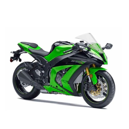
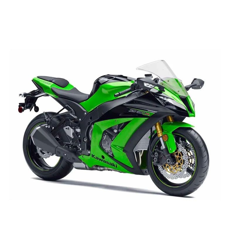
Kawasaki ZX-10R 2011-2013 — Service & Repair Manual with Wiring Diagrams
This download contains the repair/maintenance sections and independently indexed electrical schematics for Kawasaki ZX-10R 2011-2013. All entries from the original technical index are preserved below; section names do not imply additional, unlisted procedures.
Documentation language(s): English.
Selected indexed topics: Wiring Diagram (US, CA and CAL without KIBS Models); General Information; Periodic Maintenance.
Original technical index
- SERVICE MANUAL
- General Information
- - Before Servicing
- - Model Identification
- - General Specifications
- - Technical Information-Sport-Kawasaki TRaction Control System (S-KTRC)
- - Technical Information-Power Mode
- - Technical Information-Kawasaki Intelligent anti-lock Brake System (KIBS/ZX1000K model only)
- - Technical Information - Electronic Steering Damper (ESD/ZX1000JD/KD models)
- - Unit Conversion Table
- Periodic Maintenance
- - Periodic Maintenance Chart
- - Torque and Locking Agent
- - Specifications
- - Special Tools
- - Periodic Maintenance Procedures
- Fuel System (DFI)
- - Exploded View
- - DFI System
- - DFI Parts Location
- - Specifications
- - Special Tools and Sealant
- - DFI Servicing Precautions
- - Troubleshooting the DFI System
- - DFI System Troubleshooting Guide
- - Warning Indicator Light (LED)
- - ECU
- - CAN Communication Line
- - DFI Power Source
- - Fuel Line
- - Fuel Pump
- - Fuel Injectors
- - Throttle Grip and Cables
- - Throttle Body Assy
- - Nozzle Assy
- - Air Cleaner
- - Air Line
- - Fuel Tank
- - Evaporative Emission Control System (CAL and SEA-B1 Models)
- Cooling System
- - Exploded View
- - Coolant Flow Chart
- - Specifications
- - Special Tools
- - Coolant
- - Water Pump
- - Radiator
- - Thermostat
- - Hoses and Pipes
- - Water Temperature Sensor
- Engine Top End
- - Exploded View
- - Exhaust System Identification
- - Specifications
- - Special Tools and Sealant
- - Clean Air System
- - Cylinder Head Cover
- - Camshaft Chain Tensioner
- - Camshaft, Camshaft Chain
- - Cylinder Head
- - Valves
- - Throttle Body Assy Holder
- - Muffler
- Clutch
- - Exploded View
- - Specifications
- - Special Tool and Sealant
- - Clutch Lever and Cable
- - Clutch Cover
- - Clutch
- Engine Lubrication System
- - Exploded View
- - Engine Oil Flow Chart
- - Specifications
- - Special Tools and Sealant
- - Engine Oil and Oil Filter
- - Oil Pan
- - Oil Pressure Relief Valve
- - Oil Pump
- - Oil Cooler
- - Oil Pressure Measurement
- - Oil Pressure Switch
- Engine Removal/Installation
- - Exploded View
- - Special Tool
- - Engine Removal/Installation
- Crankshaft/Transmission
- - Exploded View
- - Specifications
- - Special Tools and Sealants
- - Crankcase
- - Crankshaft and Connecting Rods
- - Pistons
- - Balancer
- - Torque Limiter
- - Starter Clutch
- - Transmission
- - External Shift Mechanism
- Wheels/Tires
- - Exploded View
- - Specifications
- - Special Tools
- - Wheels (Rims)
- - Tires
- - Hub Bearing
- Final Drive
- - Exploded View
- - Specifications
- - Special Tools
- - Drive Chain
- - Sprocket, Coupling
- Brakes
- - Exploded View
- - Specifications
- - Special Tools
- - Brake Lever, Brake Pedal
- - Calipers
- - Brake Pads
- - Master Cylinder
- - Brake Disc
- - Brake Fluid
- - Brake Hose
- - KIBS (Equipped Models)
- Suspension
- - Exploded View
- - Specifications
- - Special Tools
- - Front Fork
- - Rear Shock Absorber
- - Swingarm
- - Tie-Rod, Rocker Arm
- Steering
- - Exploded View
- - Specifications
- - Special Tools
- - Steering
- - Steering Damper
- - Steering Stem
- - Handlebar
- Frame
- - Exploded View
- - Seats
- - Fairings
- - Seat Covers
- - Fenders
- - Frame
- - Windshield
- - Guard
- - Rear View Mirrors
- - Sidestand
- - Footpeg
- Electrical System
- - Exploded View
- - Specifications
- - Special Tools and Sealant
- - Parts Location
- - Wiring Diagram (US, CA and CAL without KIBS Models)
- - Wiring Diagram (US, CA and CAL with KIBS Models)
- - Wiring Diagram (Other than US, CA and CAL without KIBS Models)
- - Wiring Diagram (Other than US, CA and CAL with KIBS Models)
- - Precautions
- - Electrical Wiring
- - Battery
- - Charging System
- - Ignition System
- - Electric Starter System
- - Lighting System
- - Air Switching Valve
- - Air Intake Solenoid Valve
- - Radiator Fan System
- - Meter, Gauge, Indicator Unit
- - Immobilizer System (Equipped Models)
- - Switches and Sensors
- - Relay Box
- - Fuse
- Self-Diagnosis System
- - Specifications
- - Special Tools
- - Self-Diagnosis
- - Main Throttle Sensor (Service Code 11)
- - Intake Air Pressure Sensor #1 (Service Code 12)
- - Intake Air Temperature Sensor (Service Code 13)
- - Water Temperature Sensor (Service Code 14)
- - Intake Air Pressure Sensor #2 (Service Code 16)
- - Crankshaft Sensor (Service Code 21)
- - Rear Wheel Rotation Sensor Signal (Service Code 24)
- - Gear Position Switch (Service Code 25)
- - Front Wheel Rotation Sensor Signal (Service Code 27)
- - Vehicle-down Sensor (Service Code 31)
- - Subthrottle Sensor (Service Code 32)
- - Oxygen Sensor - not activated (Service Code 33, Equipped Models)
- - Exhaust Butterfly Valve Actuator Sensor (Service Code 34)
- - Immobilizer Amplifier (Service Code 35, Equipped Models)
- - Blank Key Detection (Service Code 36, Equipped Models)
- - ECU Communication Error (Service Code 39)
- - Fuel Pump Relay (Service Code 46)
- - Stick Coils #1, #2, #3, #4: (Service Code 51, 52, 53, 54)
- - Radiator Fan Relay (Service Code 56)
- - Subthrottle Valve Actuator (Service Code 62)
- - Exhaust Butterfly Valve Actuator (Service Code 63)
- - Air Switching Valve (Service Code 64)
- - Oxygen Sensor Heater (Service Code 67, Equipped Models)
- - KIBS Hydraulic Unit Communication Error (Service Code 1b, KIBS Equipped Models)
- - Idle Speed Control Valve Actuator (Service Code 1C)
- - Air Intake Solenoid Valve (Service Code 2d, Equipped Models)
- - ESD (Electronic Steering Damper) ECU Communication Error (Service Code 3C, ZX1000JD/KD)
- - ESD (Electronic Steering Damper) Actuator Error (Service Code E2E, ZX1000JD/KD)
- - ESD (Electronic Steering Damper) ECU Error (Service Code E3b, ZX1000JD/KD)
- - KIBS Service Codes (KIBS Equipped Models)
- Appendix
- - Cable, Wire, and Hose Routing
- - Troubleshooting Guide
- WIRING DIAGRAMS
- PARTS CATALOG