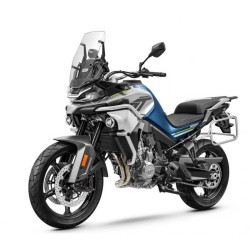
CFMOTO Papio CL from 2024 — Service and Repair Contents
The manual covers the mechanical service and repair subjects identified in the index below. Review the indexed sections for the exact technical coverage of CFMOTO Papio CL from 2024.
Technical contents
- 1 GENERAL INFORMATION
- 1.1 Operation Cautions
- 1.2 Disassembly and Assembly Cautions
- 1.3 VIN and EIN Location
- 1.4 Fuel Evaporation System Diagram
- 2 MAINTENANCE INFORMATION
- 2.1 Maintenance Information
- 2.1.1 Daily Maintenance Schedule
- 2.1.2 Break-In Maintenance Schedule
- 2.1.3 Periodic Maintenance Schedule
- 3 TECHNICAL INFORMATION
- 3.1 General Specifications
- 3.2 Engine Specifications
- 3.3 Maintenance Specifications
- 3.3.1 Front Wheel
- 3.3.2 Rear Wheel
- 3.3.3 Brake System
- 3.3.4 Suspension
- 3.3.5 Lighting and Signal System
- 3.4 Service Specifications
- 3.4.1 Valve Train+Cylinder Head
- 3.4.2 Cylinder/Piston/Piston Ring/Connecting Rod
- 3.4.3 Lubrication System
- 3.4.4 Clutch+Transmission
- 3.4.5 Air Inlet System
- 3.4.6 Electrical System
- 3.5 Tighten Torque
- 3.5.1 Tighten Torque Table for Vehicle
- 3.5.2 Tighten Torque Table for Engine
- 3.6 Consumption Materials & Assembling Materials
- 3.6.1 Vehicle Consumption Materials
- 3.6.2 Engine Consumption Materials & Assembling Materials
- 4 SEAT
- 4.1 Seat
- 5 BODY COVERING PARTS
- 5.1 Front Shock Absorber Part
- 5.2 Front Fender (Status One)
- 5.3 Front Fender (Status Two)
- 5.4 LH, RH Side Cover
- 5.5 LH, RH Front Fender
- 5.6 LH, RH Front Fender, Fuel Tank
- 5.7 Fuel Tank Fender
- 5.7.1 Remove Fuel Tank Fender
- 5.7.1.1 Remove LH, RH Front Fender Part
- 5.8 Riser Lower Plate
- 5.9 Small Sprocket Cover
- 5.10 Rear Inner Fender
- 6 FUEL TANK ASSEMBLY
- 6.1 Fuel Tank
- 6.2 Fuel Pump
- 7 LIGHTS, DASHBOARD AND SWITCHES
- 7.1 Ignition Lock Cover
- 7.2 Dashboard Lower Guard
- 7.2.1 Dashboard and Front Turn Light
- 7.3 Headlight Assembly
- 7.4 Headlight Panel
- 7.5 Headlight and Headlight Panel
- 7.6 Rear Armrest
- 7.7 Trail Light
- 7.7.1 Trail Light
- 7.8 Rear Fender Assembly
- 7.8.1 Rear Turn Light and License Light Assembly
- 7.8.2 Rear Reflector and License Bracket (Status 1)
- 7.8.3 Rear Reflector and License Bracket (Status 2)
- 7.8.4 Rear Fender
- 7.9 Left Handlebar Switch
- 7.10 Right Handlebar Switch
- 7.11 Fuel Level Sensor
- 7.12 Auxiliary Starter Relay and Fuel Pump Relay
- 7.13 Telemetics
- 7.14 Ground Cable
- 8 AIR FILTER ASSEMBLY
- 8.1 Air Filter Assembly
- 8.1.1 Removal
- 8.1.2 Inspection
- 8.1.3 Installation
- 9 ELECTRICAL SYSTEM
- 9.1 Charging System
- 9.1.1 Charging Diagram
- 9.1.2 Magneto Coil Resistance
- 9.1.3 MAG Non-loaded Performance
- 9.1.4 Regulator
- 9.2 EFI
- 9.2.1 EFI Structure
- 9.2.2 EFI System Composed of Three Subsystems:
- 9.2.2.1 Sensors
- 9.2.2.2 ECU
- 9.2.2.3 Actuators
- 9.2.3 EFI System Maintenance Notice
- 9.2.4 Service Tool
- 9.2.5 Structure and Performance of EFI Parts
- 9.2.5.1 ECU
- 9.2.5.2 Throttle Body Assembly
- 9.2.5.3 T-MAP
- 9.2.5.4 Stepper Engine
- 9.2.5.5 Cylinder Head Temp. Sensor
- 9.2.5.6 Oxygen Sensor
- 9.2.5.7 Trigger
- 9.2.5.8 Measure Trigger Resistance Value
- 9.2.5.9 Fuel Injector
- 9.2.5.10 Ignition Coil
- 9.2.5.11 Fuel Pump
- 9.2.5.12 Gear Sensor
- 9.2.6 Self-Diagnosis of EFI System
- 9.2.6.1 MIL
- 9.2.7 Fault Code Table
- 9.3 Normal Troubles
- 9.3.1 Trouble Diagnosis In Accordance With Engine Error
- 10 MUFFLER ASSEMBLY
- 10.1 Muffler
- 10.1.1 Exhaust Pipe Assembly
- 10.1.2 Rear Muffler Body Assembly
- 10.2 Service
- 11 WHEELS AND BRAKE SYSTEM
- 11.1 Front Wheel Assembly (Without Front Gear Ring)
- 11.2 Front Wheel Assembly (With Front Gear Ring)
- 11.3 Front Wheel Bearing
- 11.4 Wheel Balance Adjustment
- 11.5 Rear Wheel Assembly (Without Rear Gear Ring)
- 11.5.1 Rear Wheel Sprocket and Rear Brake Disc
- 11.6 Rear Wheel Assembly (With Rear Gear Ring)
- 11.6.1 Rear Wheel Sprocket and Rear Brake Disc
- 11.6.2 Rear Wheel Sprocket Inspection
- 11.7 Front/Rear Wheel and Brake Disc Inspection
- 11.7.1 Tire Pressure Inspection
- 11.7.2 Tire Inspection
- 11.7.3 Wheel Bearing Inspection
- 11.7.3.1 Front Wheel
- 11.7.3.2 Rear Wheel
- 11.7.4 Brake Pad Inspection
- 11.8 Front/Rear Brake Assembly (Without ABS)
- 11.8.1 Front Brke Assembly
- 11.8.2 Rear Brake Assembly
- 11.8.2.1 Remove RH Front Footrest Bracket Assembly
- 11.9 MAB Hydraulic Brake Assembly (ABS)
- 11.9.1 MAB Execution Unit
- 11.9.2 Rear Brake Caliper Assembly
- 11.9.3 Rear Brake Master Cylinder Assembly
- 11.9.3.1 RH Front Footrest Bracket Disassembly
- 11.9.4 Hand Brake Pump Assembly
- 11.9.5 Front Brake Caliper Assembly
- 11.10 Front Brake Assembly Inspection
- 11.10.1 Brake Hose, Hose Damage and Installation Inspection
- 11.10.2 Brake Performance Inspection
- 11.10.3 Front Brake Fluid Level Inspection
- 11.10.4 Brake Fluid Replacement
- 11.10.5 Front Brake Lever Free Play
- 11.10.6 Front Brake Pad Inspection
- 11.11 Rear Brake Assembly Inspection
- 11.11.1 Rear Brake Fluid Level Inspection
- 11.11.2 Rear Brake Fluid Replacement
- 11.11.3 Rear Brake Pedal Free Play
- 11.11.4 Rear Brake Pad Inspection
- 12 SHOCK ABSORBER AND REAR FORK
- 12.1 Side Stand
- 12.2 Chain
- 12.3 Rear Fork and Rear Shock Absorber Diagram
- 12.4 Rear Shock Absorber
- 12.5 Rear Shock Absorber Adjustment
- 12.6 Rear Fork
- 12.7 Chain Slider
- 12.8 Front Shock Absorber
- 12.9 Chain Service
- 12.9.1 Chain Installation
- 12.9.2 Clean Service of Chain
- 12.9.3 Chain Inspection
- 12.9.4 Chain Adjustment
- 13 ENGINE
- 13.1 Special Tool for Engine
- 13.2 Remove Engine from Vehicle
- 13.3 Engine Disassembly
- 13.3.1 Engine Oil Drain
- 13.3.2 Ignition TDC Adjustment
- 13.3.3 Starter Motor Removal
- 13.3.4 Starter Dual Gear Removal
- 13.3.5 Magneto Rotor Removal
- 13.3.6 Magneto Stator Removal
- 13.3.7 Gear Sensor Removal
- 13.3.8 Oil Filter Removal
- 13.3.9 Clutch Removal
- 13.3.10 Oil Pump Removal
- 13.3.11 Oil Pump Drive Gear and Primary Drive Gear Removal
- 13.3.12 Balance Shaft Nut Removal
- 13.3.13 Timing Chain Tensioner Removal
- 13.3.14 Spark Plug Removal
- 13.3.15 Cylinder Head Cover Removal
- 13.3.16 Cylinder Head Removal
- 13.3.17 Timing Chain Removal
- 13.3.18 Cylinder Body Removal
- 13.3.19 Piston Removal
- 13.3.20 Gearshift Assembly Removal
- 13.3.21 Crankcase Disassembly
- 13.3.22 Transmission Removal
- 13.4 Engine Inspection
- 13.4.1 Valve Clearance Adjustment
- 13.4.2 Cylinder Head Cover Assembly Inspection
- 13.4.3 Camshaft Inspection
- 13.4.4 Cylinder Head Assembly Inspection
- 13.4.5 One-way Valve Assembly Inspection (EU5)
- 13.4.6 Cylinder Body Inspection
- 13.4.7 Piston Inspection
- 13.4.8 Crankshaft Connecting Rod Assembly Inspection
- 13.4.9 Balance Shaft Drive Gear Inspection
- 13.4.10 Balance Shaft Assembly Inspection
- 13.4.11 Magneto Rotor Inspection
- 13.4.12 Overriding Clutch Inspection
- 13.4.13 Starter Driven Gear, Dual Gear and Dual Gear Shaft Inspection
- 13.4.14 Clutch Parts Inspection
- 13.4.15 Transmission Inspection
- 13.4.16 Crankcase Inspection
- 13.4.17 Tensioner Inspection
- 13.4.18 Speed Sensor Inspection (Vehicle is not equipped with ABS)
- 13.4.19 Magneto Stator Inspection
- 13.5 Engine Assembly
- 13.5.1 Transmission Case Installation
- 13.5.2 Balance Shaft Installation
- 13.5.3 Crankcase Installation
- 13.5.4 Gearshift Assembly Installation
- 13.5.5 Piston Installation
- 13.5.6 Cylinder Body Installation
- 13.5.7 Magneto Rotor Installation
- 13.5.8 Dual Gear II Installation
- 13.5.9 LH Side Cover Assembly Installation
- 13.5.10 Starter Motor Installation
- 13.5.11 Cylinder Head Installation
- 13.5.12 Camshaft Installation
- 13.5.13 Cylinder Head Cover Installation
- 13.5.14 Tensioner Installation
- 13.5.15 Clutch and Primary Drive Gear Installation
- 13.5.16 Oil Pump Installation
- 13.5.17 Balance Shaft Nut Installation
- 13.5.18 RH Side Cover Installation
- 13.5.19 Oil Filter Installation
- 13.5.20 Engine Drain Bolt Installation
- 13.5.21 Gear Sensor Installation
- 13.5.22 Screw Plug and Spark Plug Installation
- 13.6 Engine Installation
- 13.7 Air Intake System
- 13.7.1 Throttle Body Removal
- 13.7.2 Throttle Valve Body Removal (EU5)
- 13.7.3 Maintenance and Service of Parts
- 13.7.4 Throttle Body Installation
- 13.7.5 Throttle Valve Body Installation (EU5)
- 13.8 Lubrication System
- 13.8.1 Engine Oil Volume Inspection
- 13.8.2 Engine Oil Replacement
- 13.8.3 Oil Strainer Inspection
- 13.8.4 Oil Pressure Inspection
- 14 HANDLEBAR, TRIPLE CLAMP ASSEMBLY
- 14.1 Special Tool
- 14.2 LH/RH Balance Block Assembly
- 14.3 Clutch Lever Assembly
- 14.4 LH Handlebar Switch Assembly
- 14.5 RH Handlebar Switch Assembly
- 14.6 Handlebar
- 14.7 Grip
- 14.7.1 LH Grip
- 14.7.2 RH Grip
- 14.8 Throttle Cable Free Play
- 14.9 Throttle Cable
- 14.10 Inspect Clutch Lever Clearance
- 14.11 Clutch Cable
- 14.12 Handlebar Interference Inspection
- 14.13 Upper Triple Clamp
- 14.13.1 Ignition Lock
- 14.14 Front Shock Absorber, Upper Triple Clamp, Front Fork Pipe Lower Triple Clamp Assembly Diagram
- 14.15 Lower Triple Clamp of Front Fork Pipe