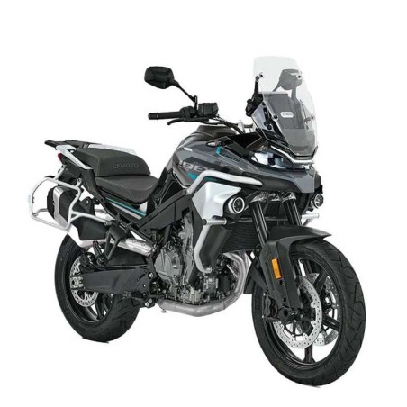
• -$10.00
CFMoto 800MT / Ibex 800 (2025+) - Service & Repair Manual (2025 Edition)
search
  • CFMoto 800MT / Ibex 800 (2025+) - Service & Repair Manual (2025 Edition)

CFMoto 800MT / Ibex 800 (2025+) - Service & Repair Manual (2025 Edition)

$29.95
$19.95 Save $10.00
No tax
Quantity

YOUTUBE Official Channel @SoloPDFcom (+18,000 subs). Trusted by mechanics worldwide using professional workshop manuals and wiring diagrams.

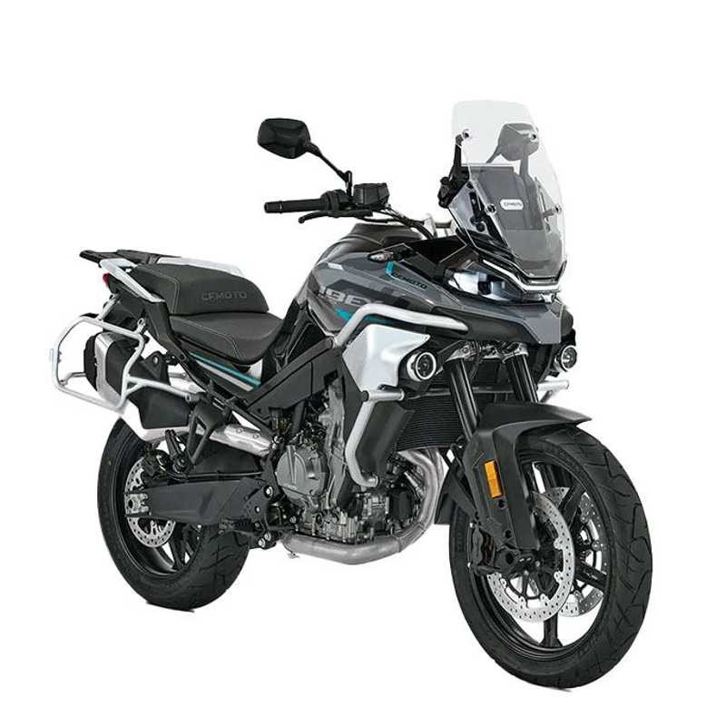
CFMoto 800MT / Ibex 800 (2025+) — Service & Repair Manual (2025 Edition)

This download includes service and repair sections in the stated 800MT(6WW5-00WX01-6000)SM-20250319 edition for CFMoto 800MT / Ibex 800 (2025+). The complete original technical index follows in the original order. The listed topics do not imply extra repair instructions or documents.

Document scope: The edition identifier 800MT(6WW5-00WX01-6000)SM-20250319 appears in the original listing. Do not generalize to other motorcycle models.

Selected original index topics: 01 GENERAL INFORMATION; 2 MAINTENANCE INFORMATION; 08 ELECTRICAL SYSTEM.
Original technical index

  • 01 GENERAL INFORMATION
  • - 1.1 Operation Cautions
  • - 1.2 Disassembly and Assembly Cautions
  • - 1.3 VIN and EIN Location
  • - 1.4 Electrical Parts Routing
  • - 1.5 Fuel Evaporation System Diagram
  • 2 MAINTENANCE INFORMATION
  • - 2.1 Reset Maintenance Interval
  • - 2.1.1 TFT Dashboard
  • - 2.1.2 MMI Dashboard
  • - 2.2 Maintenance Before Operation
  • - 2.3 Break-in Maintenance Schedule
  • - 2.4 Periodic Maintenance Schedule
  • 03 TECHNICAL INFORMATION
  • - 3.1 General Specifications
  • - 3.2 Engine Specification
  • - 3.3 Maintenance Specifications
  • - 3.3.1 Front Wheel
  • - 3.3.2 Rear Wheel
  • - 3.3.3 Brake System
  • - 3.3.4 Light, Dashboard and Switch
  • - 3.4 Service Specification
  • - 3.4.1 Valve Train&Cylinder Head
  • - 3.4.2 Lubrication System
  • - 3.4.3 Cylinder, Piston, Piston Ring and Connecting Rod
  • - 3.4.4 Clutch and Transmission
  • - 3.4.5 Cooling System
  • - 3.4.6 Air Inlet System
  • - 3.4.7 Electrical System
  • - 3.5 Tighten Torque
  • - 3.5.1 Tighten Torque Table for Vehicle
  • - 3.6 Consumption Materials&Assembling Materials
  • - 3.6.1 Vehicle Consumption Materials
  • - 3.6.2 Engine Consumption Materials&Assembling Materials
  • 04 SEAT
  • - 4.1 Seat Removal
  • - 4.2 Seat Installation
  • 05 BODY COVERING PARTS
  • - 5.1 Windshield
  • - 5.2 LH&RH Steering Panels
  • - 5.3 LH&RH Fog Light Guards
  • - 5.4 Bumpers
  • - 5.5 Fuel Tank Lower Panels and Fog Light Assy
  • - 5.6 Fuel Tank LH&RH Front Panels
  • - 5.7 Fuel Tank Guard
  • - 5.8 Dashboard
  • - 5.9 Headlight Assy
  • - 5.10 Rear Armrest
  • - 5.11 Side Box Bracket
  • - 5.12 Tail Light LH&RH Panels
  • - 5.13 Tail Light Upper Cover
  • 06 FUEL SYSTEM
  • - 6.1 Fuel Tank Removal
  • - 6.2 EVAP System
  • - 6.3 Fuel Pump
  • - 6.4 Floating Ball
  • 07 LIGHTS, DASHBOARD AND SWITCHES
  • - 7.1 Maintenance Information
  • - 7.1.1 Operation Caution
  • - 7.1.2 Inspection Standard
  • - 7.2 Trouble Shooting
  • - 7.3 Turn Light
  • - 7.4 Tail Light/Brake Light
  • - 7.5 Dashboard
  • - 7.5.1 Dashboard(IMM)
  • - 7.6 Ignition Switch
  • - 7.7 Front Brake Light Switch
  • - 7.8 LH Handlebar Switch(Status 1)
  • - 7.9 LH Handlebar Switch(Status 2)
  • - 7.10 RH Handlebar Switch(Status 1)
  • - 7.11 RH Handlebar Switch(Status 2)
  • - 7.12 Fog Light
  • - 7.13 Horn
  • - 7.14 Fuel Level Sensor
  • - 7.15 Battery
  • - 7.16 Vehicle T-BOX
  • - 7.17 Ground Wire
  • - 7.18 Start Engine Stop Control Unit
  • - 7.19 Headlight Controller
  • - 7.20 Headlight Cable
  • - 7.21 Radar Sensor (Backward - Short-range ranging sensor)
  • - 7.22 Vehicle Control Unit
  • - 7.22.1 BCM Fault and Detection
  • 08 ELECTRICAL SYSTEM
  • - 8.1 Service Tool
  • - 8.2 Charging System
  • - 8.2.1 Charging Diagram
  • - 8.2.2 Magneto Coil Resistance
  • - 8.2.3 MAG Non-loaded Performance
  • - 8.2.4 Starter Relay
  • - 8.2.5 Regulator
  • - 8.3 EFI System
  • - 8.3.1 EFI Structure
  • - 8.3.1.1 Sensors
  • - 8.3.1.2 ECU
  • - 8.3.1.3 Actuators
  • - 8.3.2 EFI System Maintenance Notice
  • - 8.3.3 Structure and Performance of EFI Parts
  • - 8.3.3.1 ECU
  • - 8.3.3.2 Throttle Assy
  • - 8.3.3.3 Air Intake Pressure Sensor
  • - 8.3.3.4 Air Intake Temperature Sensor
  • - 8.3.3.5 Water Temp. Sensor
  • - 8.3.3.6 Oxygen Sensor
  • - 8.3.3.7 Trigger
  • - 8.3.3.8 Fuel Pump
  • - 8.3.3.9 Fuel Injector
  • - 8.3.3.10 E-throttle
  • - 8.3.3.11 Ignition coil
  • - 8.3.4 UP6.0 Fault Code
  • - 8.4 Fault Diagnosis and Treatment
  • - 8.5 Trouble Diagnosis by Engine Error
  • 09 COOLING SYSTEM
  • - 9.1 Cooling System Diagram
  • - 9.2 Cooling System Removal
  • - 9.3 Coolant
  • - 9.4 Seal Inspection
  • - 9.5 Radiator and Water Pipes
  • - 9.6 Fan Motor Inspection
  • - 9.7 Coolant Inspection
  • - 9.8 Coolant Addition
  • - 9.9 Coolant Replacement
  • 10 MUFFLER ASSY
  • - 10.1 Muffler Removal
  • - 10.1.1 Engine Panels
  • - 10.1.2 Exhaust Pipe
  • - 10.1.3 Rear Muffler Body
  • - 10.1.4 Front Muffler Body
  • - 10.2 Muffler Inspection
  • 11 WHEELS AND BRAKE SYSTEM
  • - 11.1 Front Brake Caliper
  • - 11.2 Front Wheel
  • - 11.3 Rear Wheel
  • - 11.4 Rear Brake Caliper
  • - 11.5 Brake Master Cylinder
  • - 11.6 ABS Actuator
  • - 11.7 Hand Brake Master Cylinder Assy
  • - 11.8 Wheel Inspection
  • - 11.8.1 Front Wheel
  • - 11.8.2 Rear Wheel
  • - 11.8.3 Tire Pressure
  • - 11.8.4 Tire Appearance
  • - 11.8.5 Wheel Bearing
  • - 11.8.6 Rim
  • - 11.9 Brake System Inspection
  • - 11.9.1 Hand Master Cylinder Inspection
  • - 11.9.2 Rear Master Cylinder Inspection
  • - 11.9.3 Brake Hose Inspection
  • - 11.9.4 Brake Calipers and Brake discs Inspection
  • - 11.10 Free Play
  • - 11.10.1 Front Brake Lever Free Play
  • - 11.10.2 Rear Brake Pedal Free Play
  • 12 SHOCK ABSORBERS AND REAR FORK
  • - 12.1 Handlebar
  • - 12.2 Front Shock Absorbers
  • - 12.3 Chain
  • - 12.4 Rear Fork
  • - 12.5 Chain Inspection
  • - 12.6 Front Shock Absorber
  • - 12.7 Rear Shock Absorber
  • 13 ENGINE
  • - 13.1 Special Tools
  • - 13.2 Removing the Engine
  • - 13.3 Engine Disassembly
  • - 13.3.1 Draining the Engine Oil
  • - 13.3.2 Removing the Oil Filter
  • - 13.3.3 Removing the Starter Motor
  • - 13.3.4 Removing the Valve Cover
  • - 13.3.5 Removing Shift Shaft Sensor
  • - 13.3.6 Removing the Gear Position Sensor
  • - 13.3.7 Removing the Spacer
  • - 13.3.8 Removing the Alternator Cover
  • - 13.3.9 Removing the Torque Limiter and Starter Intermediate Gear
  • - 13.3.10 Removing the Ignition Pulse Generator
  • - 13.3.11 Removing the Heat Exchanger
  • - 13.3.12 Removing the Thermostat
  • - 13.3.13 Removing the Water Pump Impeller
  • - 13.3.14 Removing the Clutch Cover
  • - 13.3.15 Removing the Clutch Discs
  • - 13.3.16 Removing the Clutch Basket
  • - 13.3.17 Removing Locking Lever
  • - 13.3.18 Removing the Shift Shaft
  • - 13.3.19 Removing the Spark Plugs
  • - 13.3.20 Removing the Camshafts
  • - 13.3.21 Removing the Cylinder Head
  • - 13.3.22 Removing the Timing Chain Rails
  • - 13.3.23 Removing the Rotor
  • - 13.3.24 Removing the Oil Pan
  • - 13.3.25 Removing the Oil Pump Unit
  • - 13.3.26 Removing the Engine Case Downwards
  • - 13.3.27 Removing the Transmission Shafts
  • - 13.3.28 Removing Oil Spray Tube
  • - 13.3.29 Removing the Piston
  • - 13.4 Working on Individual Parts
  • - 13.4.1 Checking the Radial Clearance of Crankshaft Bearings
  • - 13.4.2 Changing the Main Bearing Shells
  • - 13.4.3 Checking the Balancer Shaft
  • - 13.4.4 Working on the Upper Section of the Engine Case
  • - 13.4.5 Working on the Lower Section of the Engine Case
  • - 13.4.6 Selecting the Main Bearing Shells
  • - 13.4.7 Installing the Primary Gear Wheel
  • - 13.4.8 Radial Shaft Seal Ring of Water Pump, Changing
  • - 13.4.9 Checking the Radial Clearance of Lower Conrod Bearing
  • - 13.4.10 Changing the Conrod Bearing
  • - 13.4.11 Checking/Measuring the Cylinder
  • - 13.4.12 Checking/Measuring the Piston
  • - 13.4.13 Checking the Piston Ring End Gap
  • - 13.4.14 Determining the Piston/Cylinder Mounting Clearance
  • - 13.4.15 Removing the Oil Pumps
  • - 13.4.16 Checking the Oil Pumps for Wear
  • - 13.4.17 Checking the Oil Pressure Control Valve
  • - 13.4.18 Installing the Oil Pumps
  • - 13.4.19 Preparing Timing Chain Tensioner for Installation
  • - 13.4.20 Checking the Timing Assembly
  • - 13.4.21 Working on the Camshaft Bearing Bridge
  • - 13.4.22 Working on the Cylinder Head
  • - 13.4.23 Checking the Cylinder Head
  • - 13.4.24 Checking the Clutch
  • - 13.4.25 Removing the Shift Drum Locating Unit
  • - 13.4.26 Checking the Shift Mechanism
  • - 13.4.27 Preassembling the Shift Shaft
  • - 13.4.28 Installing the Shift Drum Locating Unit
  • - 13.4.29 Disassembling the Main Shaft
  • - 13.4.30 Disassembling the Countershaft
  • - 13.4.31 Checking the Transmission
  • - 13.4.32 Assembling the Main Shaft
  • - 13.4.33 Assembling the Countershaft
  • - 13.4.34 Checking the Electric Starter Drive
  • - 13.4.35 Checking the Freewheel
  • - 13.4.36 Working on the Alternator Cover
  • - 13.5 Engine Assembly
  • - 13.5.1 Installing the Piston
  • - 13.5.2 Installing the Oil Spray Tube
  • - 13.5.3 Installing the Transmission Shafts
  • - 13.5.4 Installing the Lower Engine Case
  • - 13.5.5 Installing the Oil Pump Unit
  • - 13.5.6 Installing the Oil Pan
  • - 13.5.7 Installing the Rotor
  • - 13.5.8 Installing the Timing Chain Rails
  • - 13.5.9 Installing the Cylinder Head
  • - 13.5.10 Installing the Camshafts
  • - 13.5.11 Checking the Valve Clearance
  • - 13.5.12 Adjusting the Valve Clearance and Cleaning the Oil Screen
  • - 13.5.13 Installing the Spark Plugs
  • - 13.5.14 Installing the Shift Shaft
  • - 13.5.15 Installing the Locking Lever
  • - 13.5.16 Installing the Clutch Basket
  • - 13.5.17 Installing the Clutch Discs
  • - 13.5.18 Installing the Clutch Cover
  • - 13.5.19 Mounting the Water Pump Cover
  • - 13.5.20 Installing the Thermostat
  • - 13.5.21 Installing the Heat
  • - 13.5.22 Installing the Crankshaft Speed Sensor
  • - 13.5.23 Installing the Torque Limiter and the Starter Intermediate Gear
  • - 13.5.24 Installing the Alternator Cover
  • - 13.5.25 Installing the Spacer
  • - 13.5.26 Installing the Gear Position Sensor
  • - 13.5.27 Installing the Shift Shaft Sensor
  • - 13.5.28 Installing the Valve Cover
  • - 13.5.29 Installing the Starter Motor
  • - 13.5.30 Installing the Oil Filter
  • - 13.5.31 Installing the Oil Drain Plug
  • 14 HANDLEBAR AND TRIPLE CLAMPS
  • - 14.1 Handlebar
  • - 14.1.1 LH Handlebar Switch
  • - 14.1.2 RH Handlebar Switch
  • - 14.2 Throttle Grip
  • - 14.3 Handlebar Inspection
  • - 14.3.1 Handlebar Interference Inspection
  • - 14.4 Triple Clamps and Front Forks