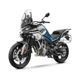
Cfmoto 650 ADVentura from 2022 - Service Manual - Repair Manual
Digital technical documentation with sections on Notice, Removal & Installation Attention, Model Identification. Review the complete contents below for the systems and procedures covered.
Manual contents
- 1 GENERAL INFORMATION
- - 1.1 Notice
- - 1.2 Removal & Installation Attention
- - 1.3 Model Identification
- - 1.4 General Specifcations
- - 1.5 Unit Conversion Table
- 2 PERIODIC MAINTENANCE
- - 2.1 Periodic Maintenance Chart
- - 2.2 Torque Specifcations for tighten parts
- - 2.3 Standard Data & Service limit
- - 2.4 Special Tool
- - 2.5 Ele ctronic Fuel Injection
- - 2.5.1 Air Filter Element Cleaning
- - 2.5.2 Throttle Control System Inspection
- - 2.5.3 Idle Speed Inspection
- - 2.5.4 Fuel Line Inspection (fuel leak, damage, installation condition)
- - 2.6 Cooling System
- - 2.6.1 Coolant Level Inspection
- - 2.6.2 Radiator Hose Damage and Installation Con-dition Inspection
- - 2.7 Cylinder Head
- - 2.7.1 Valve Clearance Inspection
- - 2.7.2 Valve Clearance Adjustment
- - 2.8 Clutch
- - 2.8.1 Clutch Operation Inspection
- - 2.9 Wheels/Tires
- - 2.9.1 Air Pressure Inspection
- - 2.9.2 Wheel/Tire Damage Inspection
- - 2.9.3 Tire Tread Wear, Abnormal Wear Inspec-tion
- - 2.9.4 Wheel Bearing Damage Inspection
- - 2.10 Drive Train
- - 2.10.1 Drive Chain Lubrication Condition Inspection
- - 2.10.2 Drive Train Slack Inspection
- - 2.10.3 Drive Chain Slack Adjustment
- - 2.11 Wheel Alignment Inspection
- - 2.12 Drive Chain Wear Inspection
- - 2.13 Chain Guide Inspection
- - 2.14 Brake System
- - 2.14.1 Brake Fluid Leak (Brake Hose and Pipe)Inspection
- - 2.14.2 Brake Hose and Pipe Damage and Installation Condition Inspection
- - 2.14.3 Brake Operation Inspection
- - 2.14.4 Brake Fluid Level Inspection
- - 2.14.5 Brake Pad Wear Inspection
- - 2.14.6 Brake Light Switch Operation Inspection
- - 2.15 Suspensions
- - 2.15.1 Front Forks/Rear Shock Absorber Opera-tion Inspection
- - 2.15.2 Front Fork Oil Leak Inspection
- - 2.15.3 Rear Shock Absorber Oil Leak Inspection
- - 2.16 Steering System
- - 2.16.1 Steering Play Inspection
- - 2.16.2 Steering Play Adjustment
- - 2.16.3 Steering Stem Bearing Lubrication
- - 2.17 Electrical System
- - 2.17.1 Spark Plug Condition Inspection
- - 2.17.2 Lights and Switches Operation Inspection
- - 2.17.3 Headlight axis inspection
- - 2.17.4 Side stand switch Operation inspection
- - 2.17.5 Engine stop switch Operation inspection
- - 2.18 Others
- - 2.18.1 Chassis Parts lubrication
- - 2.18.2 Bolts, Nuts and Fasteners Tightness Inspection
- - 2.19 Replacement Parts
- - 2.19.1 Air Filter Element Replacement
- - 2.19.2 Fuel hose Replacement
- - 2.19.3 Coolant Change
- - 2.19.4 Radiator Hose and O-ring Replacement
- - 2.19.5 Engine Oil Replacement
- - 2.19.6 Oil Filter Replacement
- - 2.19.7 Brake Hose and Pipe Replacement
- - 2.19.8 Brake Fluid Replacement
- - 2.19.9 Master Cylinder Rubber Parts Replacement
- - 2.19.10 Caliper Rubber Parts Replacement
- - 2.19.11 Spark Plug Replacement
- 3-1 EFI SYSTEM
- - 3.1 Composition of EFI system
- - 3.2 ECU Pin and Function
- - 3.3 EFI Specifications
- - 3.4 Maintanence Tool
- - 3.5 EFI Servicing Precautions
- - 3.6 EFI Malfunction Excluded
- - 3.6.1 Outline
- - 3.6.2 EFI Diagnosis Process Chart
- - 3.6.3 Sample Diagnosis Sheet
- - 3.6.4 EFI System Trouble Shooting Guide
- - 3.7 Self-diagnosis
- - 3.7.1 Self-diagnosis Outline
- - 3.7.2 Trouble Code Chart
- - 3.7.3 Solutions
- - 3.8 EFI System Service
- - 3.8.1 Throttle Position Sensor Service
- - 3.8.2 T-MAP Sensor Service
- - 3.8.3 Water Temperature Sensor Service
- - 3.8.4 Crankshaft Position Sensor Service
- - 3.8.5 Speed Sensor Service
- - 3.8.6 Roll-over Sensor Service
- - 3.8.7 Oxygen Sensor Service
- - 3.8.8 Ignition Coil Service
- - 3.8.9 MIL Service
- - 3.8.10 ECU Service
- - 3.8.11 High pressure fuel pipe service
- - 3.8.12 Fuel pump service
- - 3.8.13 Fuel Injector Service
- - 3.8.14 Throttle Grip and Cables Service
- - 3.8.15 Throttle Body Assy
- 3-2 EFI SYSTEM
- - 3.1 Composition of EFI System
- - 3.2 ECU Pin and Function
- - 3.3 EFI Specifications
- - 3.4 Maintanence Tool
- - 3.5 EFI Servicing Precautions
- - 3.6 EFI Malfunction Excluded
- - 3.6.1 Outline
- - 3.6.2 EFI Diagnosis Process Chart
- - 3.6.3 Sample Diagnosis Sheet
- - 3.6.4 EFI System Trouble Shooting Guide
- - 3.7 Self-diagnosis
- - 3.7.1 Self-diagnosis Outline
- - 3.7.2 Trouble Code Chart
- - 3.7.3 Solutions
- - 3.8 EFI System Service
- - 3.8.1 Throttle Position Sensor Service
- - 3.8.2 T-MAP Sensor Service
- - 3.8.3 Water Temperature Sensor Service
- - 3.8.4 Crankshaft Position Sensor Service
- - 3.8.5 Speed Sensor Service
- - 3.8.6 Roll-over Sensor Service
- - 3.8.7 Oxygen Sensor Service
- - 3.8.8 Ignition Coil Service
- - 3.8.9 MIL Service
- - 3.8.10 ECU Service
- - 3.8.11 High pressure fuel pipe service
- - 3.8.12 Fuel pump service
- - 3.8.13 Fuel Injector Service
- - 3.8.14 Throttle Grip and Cables Service
- - 3.8.15 Throttle Body Assy
- 4 COOLING SYSTEM
- - 4.1 Exploded View
- - 4.2 Coolant Flow Chart
- - 4.3 Specifications
- - 4.4 Special tool
- - 4.5 Coolant
- - 4.5.1 Coolant Deterioration Inspection
- - 4.5.2 Coolant Level Inspection
- - 4.5.3 Coolant Draining
- - 4.5.4 C oolant Filling
- - 4.5.5 Pressure Testing
- - 4.5.6 Cooling System Flushing
- - 4.5.7 Coolant Reserve Tank Removal/Installation
- - 4.6 Water Pump Remova
- - 4.6.1 Water Pump Removal
- - 4.6.2 Water Pump Installation
- - 4.6.3 Mechanical Seal Inspection
- - 4.6.4 Water Pump Housing Disassembly
- - 4.6.5 Water Pump Housing Assembly
- - 4.6.6 Impeller Assembly
- - 4.6.7 Pump Impeller Inspection
- - 4.7 Radiator
- - 4.7.1 Radiator and Radiator Fan Removal
- - 4.7.2 Radiator and Radiator Fan Installation
- - 4.7.3 Radiator Inspection
- - 4.7.4 Radiator Cap Inspection
- - 4.7.5 Radiator Filler Neck Inspection
- - 4.8 Thermostat
- - 4.8.1 Thermostat Removal
- - 4.8.2 Thermostat Installation
- - 4.8.3 Thermostat Inspection
- - 4.9 Hose and Pipes
- - 4.9.1 Hose Installation
- - 4.9.2 Hose Inspection
- - 4.10 Coolant Temperature Sensor
- - 4.10.1 Coolant Temperature Sensor Removal/Installation
- - 4.10.2 Coolant Temperature Sensor Inspection
- 5 ENGINE TOP END
- - 5.1 Exploded View
- - 5.2 Specifications
- - 5.3 Special tools and sealing glue
- - 5.4 Cylinder Head Cover
- - 5.4.1 Cylinder Head Ccover Removal
- - 5.4.2 Cylinder Head Cover Installation
- - 5.5 Timing Chain Tensioner
- - 5.5.1 Timing Chain Tensioner Removal
- - 5.5.2 Timing Chain Tensioner Installation
- - 5.6 Camshaft/Timing Chain
- - 5.6.1 Camshaft Removal
- - 5.6.2 Camshaft Installation
- - 5.6.3 Camshaft and Sprocket Assembly
- - 5.6.4 Camshaft/Camshaft Cap Wear
- - 5.6.5 Camshaft Runout
- - 5.6.6 Camshaft wear
- - 5.6.7 Camshaft Chain Removal
- - 5.7 Cylinder head
- - 5.7.1 Cylinder Compression Measurement
- - 5.7.2 Cylinder Head Removal
- - 5.7.3 Cylinder head installation
- - 5.7.4 Cylinder Head wear
- - 5.8 Valves
- - 5.8.1 Valve Clearance Inspection
- - 5.8.2 Valve Clearance Adjustment
- - 5.8.3 Valve Removal
- - 5.8.4 Valve Installation
- - 5.8.5 Valve Guide Removal
- - 5.8.6 Valve Guide Installation
- - 5.8.7 Valve-to-Guide Clearance Measurement (Wobble Method)
- - 5.8.8 Valve Seat Inspection
- - 5.8.9 Valve Seat Repair
- - 5.9 Cylinder body/piston
- - 5.9.1 Cylinder Removal
- - 5.9.2 Cylinder Installation
- - 5.9.3 Piston Removal
- - 5.9.4 Piston installation
- - 5.9.5 Cylinder Wear
- - 5.9.6 Piston Ring, Piston Ring Groove Wear
- - 5.9.7 Piston Ring Groove Width
- - 5.9.8 Piston Ring Thickness
- - 5.9.9 Piston Ring End Gap
- - 5.10 Intake manifold
- - 5.10.1 Intake manifold installation
- 6 CLTUCH
- - 6.1 Exploded View
- - 6.2 Specifcations
- - 6.3 Special Tool and Sealant
- - 6.4 Clutch Cover
- - 6.4.1 Clutch Cover Removal
- - 6.4.2 Right Clutch Cover Installation
- - 6.4.3 Release Shaft Removal
- - 6.4.4 Release Shaft Installation
- - 6.4.5 Right Clutch Cover Disassembly
- - 6.4.6 Clutch Cover Assembly
- - 6.5 Clutch
- - 6.5.1 Clutch Removal
- - 6.5.2 Clutch Installation
- - 6.5.3 Clutch Plate Wear, Damage Inspection
- - 6.5.4 Clutch Plate Warp Inspection
- - 6.5.5 Clutch Spring Free Length Measurement
- - 6.5.6 Clutch Housing Finger Inspection
- - 6.5.7 Clutch Housing Spline Inspection
- 7 ENGINE LUBRICATION SYSTEM
- - 7.1 Exploded View
- - 7.2 Engine Oil Flow Chart
- - 7.3 Specifcations
- - 7.4 Special Tools and Sealant
- - 7.5 Engine Oil and Oil Filter
- - 7.5.1 Oil Level Inspection
- - 7.5.2 Engine Oil Change
- - 7.5.3 Oil Filter Replacement
- - 7.6 Oil Pan
- - 7.6.1 Oil Pan Removal
- - 7.6.2 Oil Pan Installation
- - 7.7 Oil Pressure Relief Valve
- - 7.7.1 Oil Pressure Relief Valve Removal
- - 7.7.2 Oil Pressure Relief Valve Installation
- - 7.7.3 Oil Pressure Relief Valve Inspection
- - 7.8 Oil Pump
- - 7.8.1 Oil Pump Removal
- - 7.8.2 Oil Pump Installation
- - 7.9 Oil Pressure Measurement
- - 7.10 Oil Pressure Warning Switch
- - 7.10.1 Oil Pressure Switch Removal
- - 7.10.2 Oil Pressure Switch Installation
- 8 ENGINE REMOVAL AND INSTALLATION
- - 8.1 Exploded view
- - 8.2 Engine Removal/Installation
- - 8.2.1 Engine Removal
- - 8.2.2 Engine installation(Pic.8-2)
- 9 CRANKSHAFT /TRANSMISSION
- - 9.1 Exploded view
- - 9.2 Specification
- - 9.3 Crankcase Splitting
- - 9.3.1 Crankcase Splitting
- - 9.3.2 Crankcase Assembly
- - 9.4 Crankshaft and Connecting Rods
- - 9.4.1 Crankshaft Removal
- - 9.4.2 Crankshaft Installation
- - 9.4.3 Connecting Rod Removal
- - 9.4.4 Connecting Rod Installation
- - 9.4.5 Connecting Rod Bend
- - 9.4.6 Connecting Rod Twist
- - 9.4.7 Connecting Rod Big End Side Clearance
- - 9.4.8 Crankpin/Connecting Rod Big End Bearing Insert Wear
- - 9.4.9 Crankshaft Side Clearance
- - 9.4.10 Crankshaft Runout
- - 9.4.11 Crankshaft Main Bearing Insert/Journal Wear
- - 9.5 Balance shaft
- - 9.5.1 Balance shaft removal
- - 9.5.2 Balance shaft installation
- - 9.5.3 Balance shaft neck/Balance bearing wearing
- - 9.6 Transmission
- - 9.6.1 Shift Pedal Removal
- - 9.6.2 Shift Pedal Installation
- - 9.6.3 External Shift Mechanism Removal
- - 9.6.4 External Shift Mechanism Installation
- - 9.6.5 External Shift Mechanism Inspection
- - 9.6.6 Transmission Assy Removal
- - 9.6.7 Transmission Assy Disassembly
- - 9.6.8 Transmission Assy Assembly
- - 9.6.9 Transmission Assy Installation
- - 9.6.10 Transmission Shaft Disassembly
- - 9.6.11 Transmission Shaft Assembly
- - 9.6.12 Shift Fork Bending
- - 9.6.13 Shift Fork/Gear Groove Wear
- - 9.6.14 Shift Fork Guide Pin/Drum Groove Wear
- - 9.6.15 Gear Dog and Gear Dog Hole Damage
- - 9.6.16 Ball and Needle Bearing Replacement
- - 9.6.17 Ball and Needle Bearing Wear
- 10 TIRE AND RIM
- - 10.1 Exploded view
- - 10.2 Specifications and service limit
- - 10.3 Special tool
- - 10.4 Wheel (Rim)
- - 10.4.1 Front wheel removal
- - 10.4.2 Front Wheel Installation
- - 10.4.3 Rear Wheel Removal
- - 10.4.4 Rear Wheel Installation
- - 10.5 Wheel Inspection
- - 10.5.1 Axle Inspection
- - 10.5.2 Balance Inspection
- - 10.5.3 Balance Adjustment
- - 10.5.4 Balance Weight Removal
- - 10.5.5 B alance Weight Installation
- - 10.6 Tire Pressure Inspection/Adjustment
- - 10.6.1 Tire Removal
- - 10.6.2 Tire Installation
- - 10.6.3 Tire Repair
- - 10.7 Hub Bearing
- - 10.7.1 Hub Bearing Removal
- - 10.7.2 Hub Bearing Installation
- - 10.7.3 Hub Bearing Inspection
- 11 CHAIN DRIVE SYSTEM
- - 11.1 Exploded view
- - 11.2 Chain specification and service limit
- - 11.3 Special tool
- - 11.4 Drive Chain
- - 11.4.1 Drive Chain Slack Inspection
- - 11.4.2 Drive Chain Slack Adjustment
- - 11.4.3 Wheel Alignment Inspection/Adjustment
- - 11.4.4 Drive Chain Wear Inspection
- - 11.4.5 Drive Chain Lubrication
- - 11.4.6 Drive Chain Removal
- - 11.4.7 Drive Chain Installation
- - 11.5 Sprocket, Coupling
- - 11.5.1 Engine Sprocket Removal
- - 11.5.2 Engine Sprocket Installation
- - 11.5.3 Rear Sprocket Removal
- - 11.5.4 Rear Sprocket Installation
- - 11.5.5 Coupling Installation
- - 11.5.6 Coupling Bearing Removal
- - 11.5.7 Coupling Bearing Installation
- - 11.5.8 Coupling Bearing Inspection
- - 11.5.9 Coupling Bearing Oil Seal
- - 11.5.10 Coupling Damper Inspection
- - 11.5.11 Sprocket Wear Inspection
- - 11.5.12 Rear Sprocket Warp Inspection
- 12 BREAKING SYSTEM
- - 12.1 Front braking explosive view
- - 12.2 Rear braking exploded view
- - 12.3 Specification
- - 12.4 Special tool
- - 12.5 Brake Lever/Break padel
- - 12.5.1 Brake Lever Position Adjustment
- - 12.5.2 Brake Pedal Position Inspection
- - 12.5.3 Brake Pedal Position Adjustment
- - 12.5.4 Brake Pedal Removal
- - 12.5.5 Brake Pedal Installation
- - 12.6 Breaking Caliper
- - 12.6.1 Front Caliper Removal
- - 12.6.2 Rear Caliper Removal
- - 12.6.3 Front Caliper Disassembly
- - 12.6.4 Front Caliper Assembly
- - 12.6.5 Rear Caliper Disassembly
- - 12.6.6 Rear Caliper Assembly
- - 12.6.7 Caliper Fluid Seal Damage
- - 12.6.8 Rear brake caliper dust cover and sliding cover damaged
- - 12.6.9 Caliper Piston and Cylinder Damage
- - 12.6.10 Rear Caliper Holder Shaft Wear
- - 12.7 Brake Pad
- - 12.7.1 Front Brake Pad Removal
- - 12.7.2 Front Brake Pad Installation
- - 12.7.3 Rear Brake Pad Removal
- - 12.7.4 Rear Brake Pad Installation
- - 12.7.5 Brake Pad Wear Inspection
- - 12.8 Master Cylinder
- - 12.8.1 Front Master Cylinder Removal
- - 12.8.2 Front Master Cylinder Installation
- - 12.8.3 Rear Master Cylinder Removal
- - 12.8.4 Rear Master Cylinder Installation
- - 12.8.5 Front Master Cylinder Disassembly
- - 12.8.6 Rear Master Cylinder Disassembly
- - 12.8.7 Master Cylinder Assembly
- - 12.9 Master Cylinder Inspection
- - 12.10 Brake Disc
- - 12.10.1 Brake Disc Removal
- - 12.10.2 Brake Disc Installation
- - 12.10.3 Brake Disc Wear
- - 12.10.4 Brake Disc Warp
- - 12.11 Brake Fluid
- - 12.11.1 Brake Fluid Level Inspection
- - 12.11.2 Brake Fluid Replacement
- - 12.12 Drain out the air in pipes
- - 12.13 Braking hose
- - 12.13.1 Brake Hose Removal/Installation
- - 12.13.2 Brake Hose Inspection
- - 12.14 ABS Trouble code
- 13 SUSPENSION SYSTEM
- - 13.1 Front fork exploded view
- - 13.2 Rearswing arm exploded view
- - 13.3 Specifications
- - 13.4 Special tool
- - 13.5 Front Shock absorber
- - 13.5.1 Front Shock absorber removal
- - 13.5.2 Front shock absorber installation
- - 13.6 Rear shock absorber
- - 13.6.1 Spring Preload Adjustment
- - 13.6.2 Rear Shock Absorber Removal
- - 13.6.3 Rear Shock Absorber Installation
- - 13.6.4 Rear Shock Absorber Inspection
- - 13.7 Swingarm
- - 13.7.1 Swingarm Removal
- - 13.7.2 Swingarm Installation
- - 13.7.3 Swingarm Bearing Removal
- - 13.7.4 Swingarm Bearing Installation
- - 13.7.5 Swingarm Bearing, Sleeve Inspection
- - 13.7.6 Swingarm Bearing Lubrication
- - 13.8 Chain Guide Inspection
- 14 STEERING SYSTEM
- - 14.1 Exploded view
- - 14.2 Special tool
- - 14.3 Steering bearing removal
- - 14.4 Steering bearing installation
- - 14.5 Steering Bearing Lubrication
- - 14.6 Steering Stem Warp
- - 14.7 Handlebar
- - 14.7.1 Handlebar Removal
- - 14.7.2 Handlebar Installation
- - 14.8 Clutch lever assy installation
- 15 BODY COVERING
- - 15.1 Seat removal and installation
- - 15.2 Frame plate removal and installation
- - 15.3 Seat side plate removal and installation
- - 15.4 Seat lock removal and installation
- - 15.5 Fuel tank side plate removal and installation
- - 15.6 Radiator front plate removal and installation
- - 15.7 Reservior side plate removal and installation
- - 15.8 Inner plate removal and installation
- - 15.9 Windshield removal and installation
- - 15.10 Head light upper cover removal and installation
- - 15.11 Head cover removal and installation
- - 15.12 Front lower plate removal and installation.
- - 15.13 Front and rear steering light removal and installation (LH).
- - 15.14 Front plate removal and installation Front plate LH removal
- - 15.15 Steering light mounting bracket removal and installation
- - 15.16 Headlight removal and installation
- - 15.17 Dashboard removal and installation
- - 15.18 Dashboard cover removal and in-stallation
- - 15.19 Rediator rear side plate removal and installation.
- - 15.20 Radiator rear mid plate removal and installation
- - 15.21 Front fender removal and installa-tion
- - 15.22 Engine side plate removal and in-stallation
- - 15.23 Rear rocker arm fender removal and installation
- - 15.24 Rear handlebar removal and instal-lation
- - 15.25 Taillight side plate removal and installation
- - 15.26 Taillight removal and installation
- - 15.27 Rear fender removal and installation
- - 15.28 Frame bottom plate removal and installation
- - 15.29 Fuel tank removal and installation
- - 15.30 Rearview mirror removal and in-stallation
- - 15.31 Frame inspection
- 16 ELECTRIC SYSTEM
- - 16.1 Electric system form
- - 16.2 Special tool
- - 16.3 Part position
- - 16.4 Caution
- - 16.5 Wire basic
- - 16.6 Battery
- - 16.7 Charging System
- - 16.8 Ignition system
- - 16.9 Starting system
- - 16.10 Lighting system
- - 16.11 Radiator fan cooling system
- - 16.12 Switches and sensors
- - 16.13 Relay and Fuse
- 17 PDA
- - 17.1 PDA connections
- - 17.2 PDA functions
- - 17.3 Language
- - 17.4 Auto diagnosis
- - 17.5 Read DTC
- - 17.6 Clear DTC
- - 17.7 Data stream
- - 17.8 Actuator test
- - 17.9 Lamp off
- - 17.10 Read ECU ID
- - 17.11 ECU Reset