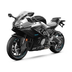
Cfmoto Papio SS from 2024 — Service and Repair Contents
Browse the service and repair documentation for Cfmoto Papio SS from 2024. Indexed subjects include engine servicing, transmissions, braking systems.
Technical contents
- 1 GENERAL INFORMATION
- 1.1 Operation Cautions
- 1.2 Disassembly and Assembly Cautions
- 1.3 VIN and EIN Location
- 1.4 Fuel Evaporation System Diagram
- 2 MAINTENANCE INFORMATION
- 2.1 Maintenance Information
- 2.1.1 Daily Maintenance Schedule
- 2.1.2 Break-In Maintenance Schedule
- 2.1.3 Periodic Maintenance Schedule
- 3 TECHNICAL INFORMATION
- 3.1 General Specifications
- 3.2 Engine Specifications
- 3.3 Maintenance Specifications
- 3.3.1 Front Wheel
- 3.3.2 Rear Wheel
- 3.3.3 Brake System
- 3.3.4 Suspension
- 3.3.5 Lighting and Signal System
- 3.4 Service Specifications
- 3.4.1 Valve Train and Cylinder Head
- 3.4.2 Cylinder/Piston/Piston Ring/Connecting Rod
- 3.4.3 Lubrication System
- 3.4.4 Clutch and Transmission
- 3.4.5 Air Inlet System
- 3.4.6 Electrical System
- 3.5 Tighten Torque
- 3.5.1 Tighten Torque Table for Vehicle
- 3.5.2 Tighten Torque Table for Engine
- 3.6 Consumption Materials & Assembling Materials
- 3.6.1 Vehicle Consumption Materials
- 3.6.2 Engine Consumption Materials & Assembling Materials
- 4 SEAT
- 4.1 Seat
- 5 BODY COVERING PARTS
- 5.1 LH Side Cover
- 5.2 LH Front Panel of Fuel Tank
- 5.3 LH Front Panel
- 5.4 Fuel Tank Guard Assembly
- 5.4.1 Remove Fuel Tank Guard Assembly
- 5.4.2 Remove LH Front Guard Part
- 6 FUEL TANK ASSEMBLY
- 6.1 Fuel Tank
- 6.2 Fuel Pump
- 7 LIGHTS,DASHBOARD AND SWITCHES
- 7.1 Pipe, LH Lower Backboard
- 7.2 Headlight Assembly
- 7.2.1 Headlight Back Board
- 7.2.2 Windshield
- 7.2.3 Headlight Panel
- 7.3 Dashboard
- 7.3.1 Low Guard, Dashboard
- 7.3.2 Remove Dashboard
- 7.4 Ignition Switch
- 7.5 Ignition Lock Cover
- 7.6 Front Turning Light
- 7.6.1 LH Front Turning Light
- 7.6.2 LH Front Turning Light(North America)
- 7.7 Rear Inner Fender
- 7.8 Rear Fender Assembly
- 7.8.1 Rear Turning Light and License Light Assembly
- 7.8.2 Rear Reflector, License Bracket (Status 1)
- 7.8.3 Rear Reflector, License Bracket (Status 2)
- 7.8.4 Rear Fender
- 7.9 Tail Light/Brake Light
- 7.9.1 Tail Light Cover Assembly, LH/RH
- 7.10 Left Handlebar Switch
- 7.11 Right Handlebar Switch
- 7.12 Fuel Level Sensor
- 7.13 Auxiliary Starter Relay and Fuel Pump Relay
- 7.14 Telemetics
- 7.15 Ground Cable
- 8 AIR FILTER ASSEMBLY
- 8.1 Air Filter Assembly
- 8.1.1 Removal
- 8.1.2 Inspection
- 8.1.3 Installation
- 9 ELECTRICAL SYSTEM
- 9.1 Charging System
- 9.1.1 Charging Diagram
- 9.1.2 Magneto Coil Resistance
- 9.1.3 MAG Non-loaded Performance
- 9.1.4 Regulator
- 9.2 EFI
- 9.2.1 EFI Structure
- 9.2.2 EFI System Composed of Three Subsystems
- 9.2.2.1 Sensors
- 9.2.2.2 ECU
- 9.2.2.3 Actuators
- 9.2.3 EFI System Maintenance Notice
- 9.2.4 Service Tool
- 9.2.5 Structure and Performance of EFI Parts
- 9.2.5.1 ECU
- 9.2.5.2 Throttle Body Assembly
- 9.2.5.3 T-MAP
- 9.2.5.4 Stepper Engine
- 9.2.5.5 Cylinder Head Temp. Sensor
- 9.2.5.6 Oxygen Sensor
- 9.2.5.7 Trigger
- 9.2.5.8 Measure Trigger Resistance Value
- 9.2.5.9 Fuel Injector
- 9.2.5.10 Ignition Coil
- 9.2.5.11 Fuel Pump
- 9.2.5.12 Gear Sensor
- 9.2.6 Self-Diagnosis of EFI System
- 9.2.6.1 MIL
- 9.2.7 Fault Code Table
- 9.2.9 Normal Troubles
- 9.2.10 Trouble Diagnosis In Accordance With Engine Error
- 10 MUFFLER ASSEMBLY
- 10.1 Muffler
- 10.1.1 Exhaust Pipe Assembly
- 10.1.2 Rear Muffler Body Assembly
- 10.2 Service
- 11 WHEELS AND BRAKE SYSTEM
- 11.1 Front Wheel Assembly (Without Front Gear Ring)
- 11.2 Front Wheel Assembly (With Front Gear Ring)
- 11.3 Front Wheel Bearing
- 11.4 Wheel Balance Adjustment
- 11.5 Rear Wheel Assembly (Without Rear Gear Ring)
- 11.5.1 Rear Wheel Sprocket and Rear Brake Disc
- 11.6 Rear Wheel Assembly (Without Rear Gear Ring)
- 11.6.1 Rear Wheel Sprocket and Rear Brake Disc
- 11.6.2 Rear Wheel Sprocket Inspection
- 11.7 Front/Rear Wheel Inspection, Brake Disc
- 11.7.1 Tire Pressure Inspection
- 11.7.2 Tire Inspection
- 11.7.3 Wheel Bearing Inspection
- 11.7.3.1 Front Wheel
- 11.7.3.2 Rear Wheel
- 11.7.4 Brake Pad Inspection
- 11.8 Front/Rear Brake Assembly (Without ABS)
- 11.8.1 Front Brke Assembly
- 11.8.2 Rear Brake Assembly
- 11.8.2.1 Remove RH Footrest Bracket Assembly
- 11.9 MAB Hydraulic Brake Assembly(ABS)
- 11.9.1 MAB Execution Unit
- 11.9.2 Rear Brake Caliper Assembly
- 11.9.3 Rear Brake Master Cylinder Assembly
- 11.9.4 Hand Brake Pump Assembly
- 11.9.5 Front Brake Caliper Assembly
- 11.10 Front Brake Assy Inspection
- 11.10.1 Brake Hose, Hose Damage and Installation Inspection
- 11.10.2 Brake Performance Inspection
- 11.10.3 Front Brake Fluid Level Inspection
- 11.10.4 Brake Fluid Replacement
- 11.10.5 Front Brake Lever Free Play
- 11.10.6 Front Brake Pad Inspection
- 11.11 Rear Brake Assy Inspection
- 11.11.1 Rear Brake Fluid Level Inspection
- 11.11.2 Change Rear Brake Fluid
- 11.11.3 Rear Brake Pedal Free Play
- 11.11.4 Rear Brake Pad Inspection
- 12 SHOCK ABSORBERS AND REAR FORK
- 12.1 Rear Fork, Rear Shock Absorber Assembly Diagram
- 12.2 LH Footrest Bracket and Gearshift Assembly
- 12.3 Side Stand
- 12.4 Rear Shock Absorber
- 12.5 Chain
- 12.5.1 Small Sprocket Guard
- 12.6 Rear Fork
- 12.7 Chain Slider
- 12.8 Chain Service
- 12.8.1 Chain Installation
- 12.8.2 Clean Service of Chain
- 12.8.3 Chain Inspection
- 12.8.4 Chain Adjustment
- 12.9 Rear Shock Absorber
- 12.10 Rear Shock Absorber Adjustment
- 13 ENGINE
- 13.1 Special Tool for Engine
- 13.2 Remove Engine from Vehicle
- 13.3 Engine Disassembly
- 13.3.1 Engine Oil Drain
- 13.3.2 Ignition TDC Adjustment
- 13.3.3 Starter Motor Removal
- 13.3.4 Starter Dual Gear Removal
- 13.3.5 Magneto Rotor Removal
- 13.3.6 Magneto Stator Removal
- 13.3.7 Gear Sensor Removal
- 13.3.8 Oil Filter Removal
- 13.3.9 Clutch Removal
- 13.3.10 Oil Pump Removal
- 13.3.11 Oil Pump Drive Gear and Primary Drive Gear Removal
- 13.3.12 Balance Shaft Nut Removal
- 13.3.13 Timing Chain Tensioner Removal
- 13.3.14 Spark Plug Removal
- 13.3.15 Cylinder Head Cover Removal
- 13.3.16 Cylinder Head Removal
- 13.3.17 Timing Chain Removal
- 13.3.18 Cylinder Body Removal
- 13.3.19 Piston Removal
- 13.3.20 Gearshift Assembly Removal
- 13.3.21 Crankcase Disassembly
- 13.3.22 Transmission Removal
- 13.4 Engine Inspection
- 13.4.1 Valve Clearance Adjustment
- 13.4.2 Cylinder Head Cover Assembly Inspection
- 13.4.3 Camshaft Inspection
- 13.4.4 Cylinder Head Assembly Inspection
- 13.4.5 One-way Valve Assembly Inspection (EU5)
- 13.4.6 Cylinder Body Inspection
- 13.4.7 Piston Inspection
- 13.4.8 Crankshaft Connecting Rod Assembly Inspection
- 13.4.9 Balance Shaft Drive Gear Inspection
- 13.4.10 Balance Shaft Assembly Inspection
- 13.4.11 Magneto Rotor Inspection
- 13.4.12 Overriding Clutch Inspection
- 13.4.13 Starter Driven Gear, Dual Gear and Dual Gear Shaft Inspection
- 13.4.14 Clutch Parts Inspection
- 13.4.15 Transmission Inspection
- 13.4.16 Crankcase Inspection
- 13.4.17 Tensioner Inspection
- 13.4.18 Speed Sensor Inspection (Vehicle is not equipped with ABS)
- 13.4.19 Magneto Stator Inspection
- 13.5 Engine Assembly
- 13.5.1 Transmission Case Installation
- 13.5.2 Balance Shaft Installation
- 13.5.3 Crankcase Installation
- 13.5.4 Gearshift Assembly Installation
- 13.5.5 Piston Installation
- 13.5.6 Cylinder Body Installation
- 13.5.7 Magneto Rotor Installation
- 13.5.8 Dual Gear II Installation
- 13.5.9 LH Side Cover Assembly Installation
- 13.5.10 Starter Motor Installation
- 13.5.11 Cylinder Head Installation
- 13.5.12 Camshaft Installation
- 13.5.13 Cylinder Head Cover Installation
- 13.5.14 Tensioner Installation
- 13.5.15 Clutch and Primary Drive Gear Installation
- 13.5.16 Oil Pump Installation
- 13.5.17 Balance Shaft Nut Installation
- 13.5.18 RH Side Cover Installation
- 13.5.19 Oil Filter Installation
- 13.5.20 Engine Drain Bolt Installation
- 13.5.21 Gear Sensor Installation
- 13.5.22 Screw Plug and Spark Plug Installation
- 13.6 Engine Installation
- 13.7 Air Intake System
- 13.7.1 Throttle Body Removal
- 13.7.2 Throttle Valve Body Removal (EU5)
- 13.7.3 Maintenance and Service of Parts
- 13.7.4 Throttle Body Installation
- 13.7.5 Throttle Valve Body Installation (EU5)
- 13.8 Lubrication System
- 13.8.1 Engine Oil Volume Inspection
- 13.8.2 Engine Oil Replacement
- 13.8.3 Oil Strainer Inspection
- 13.8.4 Oil Pressure Inspection
- 14 HANDLEBAR, TRIPLE CLAMP ASSEMBLY
- 14.1 Special Tool
- 14.2 LH Rear View Mirror
- 14.3 Clutch Lever Assembly
- 14.4 LH Handlebar Switch Assembly
- 14.5 RH Handlebar Switch Assembly
- 14.5.1 Throttle Cable Free Play
- 14.6 Throttle Cable
- 14.6.1 Clutch Lever Inspection
- 14.7 Clutch Cable
- 14.7.1 Handlebar Interference Inspection
- 14.8 Front Shock Absorber and Lower Triple Clamp, Front Fork Pipe Assembly
- 14.9 Handlebar, Upper Triple Clamp
- 14.10 Lower Triple Clamp, Front Fork Pipe