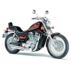
Suzuki GS1000 - Repair, Service Manual, Wiring Diagrams, Parts Catalog and Owners Manual
Digital technical documentation with sections on - SUZUKI GS1000 SERVICE MANUAL, - SUZUKI GS1000 SUPPLEMENT, - SUZUKI GS1000 C-E-S-L SERVICE MANUAL. Review the complete contents below for the systems and procedures covered.
Manual contents
- - SUZUKI GS1000 SERVICE MANUAL
- - SUZUKI GS1000 SUPPLEMENT
- - SUZUKI GS1000 C-E-S-L SERVICE MANUAL
- - SUZUKI GS1000 S SUPPLEMENT
- - SUZUKI GS1000 G PARTS CATALOGUE
- - SUZUKI GS1000 GT-GX PARTS CATALOGUE
- - SUZUKI GS1000 H-E PARTS CATALOGUE
- - SUZUKI GS1000 LN PARTS CATALOGUE
- - SUZUKI GS1000 S PARTS CATALOGUE
- - SUZUKI GS1000 SN PARTS CATALOGUE
- - SUZUKI GS1000 ST PARTS CATALOGUE
- - SUZUKI GS1000 T-HT-ET PARTS CATALOGUE
- - SUZUKI GS1000 E OWNERS MANUAL
- - SUZUKI GS1000 G OWNERS MANUAL
- CONTENTS:
- GS1000 SERVICE MANUAL
- -Suzuki GS1000 Service Manual
- -Group Index
- -General Information
- - Serial Number Location
- - Fuel, Oils & Breaking In Procedure
- - Orientation
- - Service Specifications
- -Service Specifications
- - Engine Top End
- - Engine Lower End
- - Lubrication System
- - Clutch
- - Transmission
- - Fuel System
- - Ignition System
- - Charging System
- - Lamp Wattage
- - Brakes + Wheels
- - Tire Pressure, Suspension + Frame + Steering
- - Torque Table
- -Periodic Maintenance
- - Schedule
- - Battery
- - Cylinder Head Nuts & Exhaust Pipe Bolts
- - Air Cleaner Element
- - Tappet Clearance
- - Shim Selection Chart
- - Spark Plug
- - Contact Breaker Points
- - Ignition Timing
- - Engine Oil
- - Carburetor Idle RPM
- - Engine Oil Filter
- - Clutch, Drive Chain
- - Tires
- - Brakes
- - Steering
- - Front Forks
- - Chassis Bolts & Nuts
- -Special Materials
- -Special Tools
- -Trouble Shooting
- - Engine & Chassis
- - Electrical
- -Engine
- - Engine Removal
- - Engine Remounting
- - Compression Check
- - Top End - Removal
- - Top End - Installation
- - Top End - Inspection
- - Cylinder
- - Piston & Rings
- - Lower End
- - Clutch
- - External Mechanism For Gear Shift
- - Engine Lubricaion System
- -Fuel System & Carburetors
- - Fuel Cock
- - Fuel tank
- - Carburetors
- - Troubleshooting
- -Emission Control & Regulations
- - Regulation
- - Emission Control Carburetor Components
- - General Emission Information
- -Chassis
- - Handlebar
- - Clutch Cable
- - Throttle Cable
- - Speedometer Cable
- - Tachometer Cable
- - Headlamp
- - Ignition Switch
- - Front Fork
- - Steering Stem
- - Steering Stem Bearing
- - Front Wheel
- - Front Brake Master Cylinder
- - Front Brake Caliper
- - Brake Parts To Be Periodically Replaced
- - Rear Brake Caliper
- - Rear Master Cylinder
- - Rear Wheel
- - Swinging Arm
- - Rear Shock Absorber
- -Electrical System
- - Ignition System
- - Spark Plug
- - Charging System
- - Starter System
- - Battery
- - Troubleshooting
- - Utility Switches & Devices
- - Lamp Wattage Data
- - Fuel Gauge
- - Wiring Diagram
- - Cable Routing
- -GS1000E Supplementary Service Manual
- - Contents
- - Master Cylinder
- - Caliper
- - Trouble Shooting
- -GS1000S Supplementary Service Manual
- - Contents
- - Information
- - Specifications
- - Service Data
- - Periodic Maintenance
- - Engine Removal
- - Fuel System
- - Chassis
- - Electrical
- - Wire & Cable Routing
- - Cable Routing
- - Wiring Diagram
- -GS1000L Supp;ementary Service Manual
- - Contents
- - Information
- - Specifications
- - Service Data
- - Periodic Maintenance
- - Engine Removal
- - Fuel System & Carburetors
- - Chassis
- - Electrical
- - Wire & Cable Routing
- - Wiring Diagram
- -GS1000E Supplementary Service Manual
- - Contents
- - Specifications
- - Service Data
- - Torque Table
- - Special Materials
- - Periodic Maintenance
- - Modifications
- - Emission Control & Regulations
- - Fuel System
- - Full Transistorized Ignition System
- - GS1000ST Supplentary Service Manual
- -GS1000GT Supplementary Service Manual
- - Contents
- - Specifications
- - Service Data
- - Torque Table
- - Special Materials
- - Periodic Maintenance
- - Emission Control & Regulations
- - Engine Removal & Remounting
- - Secondary Bevel Gear Assembly
- - Clutch
- - Crankcase
- - Transmission
- - Lubrication System
- - Shaft Drive
- - Final Drive Bevel Gear Assembly
- - Full-Transistorized Ignition System
- - Charging System
- - Front Fork
- - Front Master Cylinder
- - Front Caliper
- - Rear Wheel
- - Rear Swinging Arm
- - Wire & Cable Routing
- - Wiring Diagram
- -GS1000GLT Supplementary Service Manual
- - Specifications
- - Service Data
- - Fuel Cock
- - Front Fork
- - Front Master Cylinder
- - Wire & Cable Routing
- - Wiring Diagram
- -GS1000GX Supplementary Service Manual
- - Contents
- - Specifications
- - Service Data
- - Charging System
- - Wire & Cable Routing
- - Wiring Diagram
- GS1000 C-E-S-L SERVICE MANUAL
- -GS1000C
- - Forward
- - View of Suzuki GS1000
- -Group Index
- -1-General Informaion
- - Identification Table
- - Fuel, Oils, and Braking-In Procedure
- - Orientation
- - Service Specifications
- -2-Service Specifications
- - Service Specifications
- - Torque Table
- -3-Periodic Maintenance
- - Periodic Maintenance Schedule
- - Periodic Maintenance Procedures
- - Battery
- - Cylinder Head Nuts and Exhaust Pipe Bolts
- - Air Cleaner Element
- - Tappet Clearance
- - Shim Selection Chart
- - Spark Plug
- - Fuel Line
- - Contact Breaker Point
- - Ignition Timing
- - Engine Oil
- - Engine Oil Filter
- - Carburetor Idle RPM
- - Clutch
- - Drive Chain
- - Brake Hoses
- - Tires
- - Brakes
- - Steering
- - Front Forks
- - Chassis Bolts and Nuts
- -4-Special Materials
- -5-Special Tools
- -6-Troubleshooting
- - Engine and Chassis
- - Electrical
- -7-Engine
- - Engine Removal
- - Engine Remounting
- - Compression Check
- - Top End - Removal
- - Top End - Installation
- - Top End - Inspection
- - Cylinder
- - Piston and Rings
- - Lower End
- - Clutch
- - External Mechanism For Gear Shift
- - Engine Lubricaion System
- -8-Fuel System & Carburetors
- - Fuel Cock
- - Fuel Tank
- - Carburetors
- - Starter Unit
- - Pilot Circuit
- - Main Circuit
- - Float Unit
- - Needle Valve
- - Disassembly
- - Reassembly
- - Adjustment
- - Troubleshooting
- -9-Emission Control & Regulations
- - Regulation
- - Emission Control Carburetor Components
- - General Emission Information
- -10-Chassis
- - Handlebar
- - Clutch Cable
- - Throttle Cable
- - Speedometer Cable
- - Tachometer Cable
- - Speedometer and Tachometer
- - Headlamp
- - Ignition Switch
- - Front Fork
- - Steering Stem
- - Steerming Stem Bearing
- - Front Wheel
- - Front Brake Master Cylinder
- - Front Brake Caliper
- - Caliper
- - Rear Brake Caliper
- - Rear Master Cylinder
- - Rear Wheel
- - Swinging Arm
- - Rear Shock Absorber
- -11-Electrical System
- - Ignition System
- - Spark Plug
- - Charging System
- - Testing Rectifier, Regulator, & Alternator
- - Inspection Of Charging System Components
- - Starter System
- - Battery
- - Troubleshooting
- - Wiring Diagram
- -12-GS1000E
- - General Information
- - Front Brake
- - Wheel
- - Self-Cancelling Turn Signal
- - Wiring Diagram
- -13-GS1000S
- - General Information
- - Periodic Maintenance
- - Engine Removal
- - Fuel System
- - Chassis
- - Electrical
- - Wire & Cable Routing
- - Wiring Diagram
- -14-GS1000L
- - General Information
- - Periodic Maintenance
- - Engine Removal
- - Fuel System & Carburetors
- - Chassis
- - Electrical
- - Wire & Cable Diagram
- - Wiring Diagram
- PARTS CATALOGUE
- - Index
- - Overview
- - Preface
- - Colour Code
- - Fig. 1 Cylinder Head Cover
- - Fig. 2 Cylinder Head
- - Fig. 3 Cylinder
- - Fig. 4 Crankcase
- - Fig. 5 Crankcase Cover
- - Fig. 6 Oil Pump & Filter
- - Fig. 7 Crankshaft
- - Fig. 8 Starter Clutch
- - Fig. 9 Camshaft Valve
- - Fig. 10 Cam Chain
- - Fig. 11 Carburetor
- - Fig. 12 Air Cleaner
- - Fig. 13 Muffler
- - Fig. 14 Clutch
- - Fig. 15 Transmission
- - Fig. 16 Secondary Drive Gear
- - Fig. 17 Gear Shifting
- - Fig. 18 Prop Shaft Final Drive Gear
- - Fig. 19 Starter Motor
- - Fig. 20 Generator GT
- - Fig. 21 Generator GX
- - Fig. 22 Signal Generator
- - Fig. 23 Battery
- - Fig. 24 Speedometer & Tachometer
- - Fig. 25 Headlamp
- - Fig. 26 Turn Signal Lamp GT
- - Fig. 27 Turn Signal Lamp GX
- - Fig. 28 Rear Combination Lamp
- - Fig. 29 Electrical
- - Fig. 30 Wiring Harness
- - Fig. 31 Frame
- - Fig. 32 Stand
- - Fig. 33 Foot Rest
- - Fig. 34 Fuel Tank GT
- - Fig. 35 Fuel Tank GX
- - Fig. 36 Fuel Cock
- - Fig. 37 Seat GT
- - Fig. 38 Seat GX
- - Fig. 39 Front Cover GT
- - Fig. 40 Front Cover GX
- - Fig. 41 Front Fork
- - Fig. 42 Steering Stem
- - Fig. 43 Head Lamp Housing & front Fender
- - Fig. 44 Front Wheel
- - Fig. 45 Handle Bar
- - Fig. 46 Right Handle Switch
- - Fig. 47 Left Handle Switch
- - Fig. 48 Front Brake Calipers
- - Fig. 49 Front Master Cylinder
- - Fig. 50 Front Brake Hose
- - Fig. 51 Rear Swing Arm
- - Fig. 52 Rear Fender
- - Fig. 53 Rear Wheel
- - Fig. 54 Rear Calipers
- - Fig. 55 Rear Master Cylinder
- - Fig. 56 Optional Parts