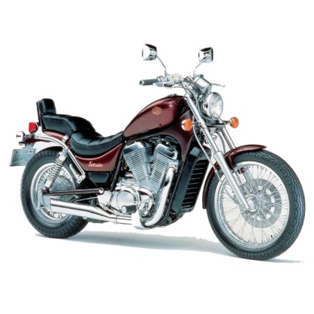
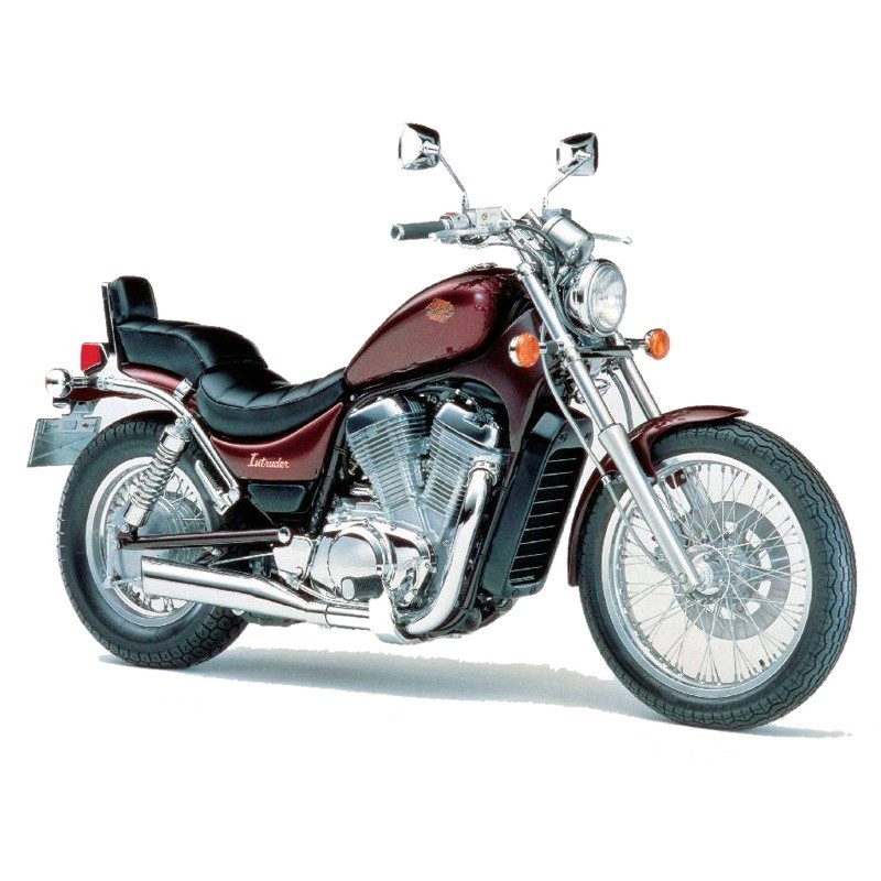
Suzuki Intruder VS700GL, VS750GL, VS800GL - Repair, Service Manual and Electrical Wiring Diagrams
Digital technical manual for the Suzuki Intruder VS700GL, VS750GL, VS800GL - Repair, Service Manual and Electrical Wiring Diagrams. Contents include 01 GENERAL INFORMATION, -Fuel, Oil And Coolant Recommendations, -Cylinder Identification. Browse the full section list below to review the systems and procedures covered.
Manual contents
- FOREWORD
- -View Of Suzuki Vs700glf
- 01 GENERAL INFORMATION
- -Serial Number Locations
- -Fuel, Oil And Coolant Recommendations
- -Breaking-In Procedures
- -Cylinder Identification
- -Special Materials
- -Precautions And General Instructions
- -Specifications
- 02 PERIODIC MAINTENANCE AND TUNE-UP PROCEDURES
- -Periodic Maintenance Schedule
- - Periodic Maintenance Chart
- - Lubrication Point
- -Maintenance And Tune-Up Procedures
- - Battery
- - Air Cleaner
- - Valve Clearance
- - Spark Plug
- - Engine Oil And Oil Filter
- - Carburetor
- - Fuel And Vapor Hose
- - Clutch
- - Cooling System
- - Final Gear Oil
- - Brakes
- - Tires
- - Steering
- - Front Fork
- - Chassis Bolts And Nuts
- 03 ENGINE
- -Compression Check
- -Engine Components Removable With The Engine In Place
- -Engine Removal And Reinstallation
- - Engine Removal
- - Engine Reinstallation
- -Engine Disassembly
- -Engine Components Inspection And Servicing
- - Cylinder Head Cover
- - Cylinder Head
- - Cylinder
- - Piston
- - Piston Ring
- - Piston Pin And Pin Bore
- - Connecting Rod
- - Crankshaft
- - Clutch
- - Generator And Signal Generator
- - Starter Clutch
- - Oil Pump
- - Transmission
- -Engine Reassembly
- - Camshaft Timing
- - Valve Rocker Arm And Shaft
- 04 SHAFT DRIVE
- -Shaft Drive
- -Secondary Bevel Gears Construction
- - Removal And Disassembly
- - Inspecti0n
- - Reassembly
- - Secondary Gears Shim Adjustment
- - Final Assembly And Remounting
- - Reassembly Information
- -Final Bevel Gears Construction
- -Final Gear Case Breather Circuit
- - Removal And Disassembly
- - Inspection
- - Reassembly
- - Final Gear Shim Adjustment
- - Final Assembly And Remounting
- - Reassembly Information
- 05 COOLING SYSTEM
- -Cooling System
- -Cooling Solution
- -Radiator And Water Hoses
- -Thermostat
- -Water Pump
- -Thermo - Sw Itch
- - Engine Thermo-Switch
- - Fan Motor
- 06 FUEL AND LUBRICATION SYSTEM
- -Fuel System
- -Fuel Cock
- -Fuel Pump
- -Fuel Pump Relay
- -Carburetor
- - Carburetor Construction
- - Specifications
- - I.D. No. Location
- - Diaphragm And Piston Operation
- - Slow System
- - Transient Enrichment System
- - Main System
- - Starter System
- - Float System
- - Disassembly
- - Needle Valve Inspection
- - Float Height Adjustment
- - Reassembly
- - Fuel Level Inspection
- - Balancing Carburetors
- -Lubrication System
- - Oil Pressure
- - Oil Sump Filter
- - Lubrication System Chart
- 07 EMISSION CONTROL INFORMATION
- -Emission Control Carburetor Components
- 08 ELECTRICAL SYSTEM
- -Charging System
- -Ignition System
- -Starter System
- -Speedometer And Instrument Panel
- -Water Temperature Unit And Indicator
- -Lamps
- -Switches
- -Battery
- 09 CHASSIS
- -Front Wheel
- -Front Brake
- -Front Fork
- -Steering Stem
- -Rear Wheel And Brake
- -Rear Suspension And Swingarm
- -Clutch Master Cylinder
- 10 SERVICING INFORMATION
- -Troubleshooting
- -Wiring Diagram
- -Cable, Harness And Hose Routing
- -Special Tools
- -Tightening Torque
- -Service Data
- 11 VS700GLE
- -View Of Vs700gle
- -Specifications
- -Periodic Maintenance Schedule
- -Shaft Drive
- -Emission Control Carburetor Components
- -Cylinder
- -Chassis
- -Service Data
- 12 VS700GLH ('87-MODEL)
- -View Of Suzuki Vs700glh
- -Specifications
- -Service Data
- -Changes
- -Cable Routing
- -Wire Harness Routing
- -Hose Routing
- -Wiring Diagram
- 13 VS750GLJ ('88-MODEL)
- -View Of Suzuki Vs760glj
- -Specifications
- -Service Data
- -Changes
- - Conrod
- - Crankshaft
- - Piston
- - Front Fork
- -Ignition System
- -Emission Control Carburetor Components
- -Wiring Diagram
- -Harness, Cable Aind Hose Routing
- -Tightening Torque
- 14 VS750GLK ('89-MODEL)
- -Service Data
- 15 VS750GLFL/GLPL ('90-MODEL) AND VS750GLFM/GLPM ('91-MODEL)
- -Service Data
- 16 VS800GLN ('92-MODEL)
- -View Of Suzuki Vs800gln
- -Specifications
- -Service Data
- -Tightening Torque
- -Periodic Maintenance Schedule
- -Features
- - Piston
- - Piston Rings
- - Conrod
- - Crankpin Bearing
- - Intake Pipe
- - Cylinder
- - Gaskets
- - Radiator
- - Radiator Hose Connection
- - Handlebar
- - Pivot Shaft
- -Wiring Diagram
- -Wire Routing
- -Label Information
- -Emission Control Carburetor Components
- -Evaporative Emission Control System
- -Canister Hose Routing
- 17 VS800GLP/R ('93/'94-MODEL)
- -Service Data
- 18 VS800GLS ('95-MODEL)
- -Specifications
- -Service Data
- -Carburetor
- -Cable Routing
- 19 VS800GLT/V ('96/'97-MODEL)
- -Specifications
- -Service Data
- -Tightening Torque
- -Charging System
- -Ignitor Unit Inspection
- -Speedometer And Instrument Panel
- -Wiring Diagram
- -Wire Harness Routing
- 20 VS800GLW/X ('98/'99-MODEL)
- -Specifications
- -Service Data
- 21 VS800GLY/K1/K2/K3 (’00/’01/’02/’03-MODEL)
- -Specifications
- -Service Data
- -Steering Stem
- -Cable Routing
- 22 VS800GLK4 ('04-MODEL)
- -Specifications
- -Service Data
- -Wiring Diagram
- 23 SV800K5 ('05-MODEL)
- -Specifications
- -Service Data
- -Wiring Harness Routing
- -Clutch Hose Routing
- -Front Brake Hose Routing
- -Handle Balancer Installation
- -Tool Holder Installation
- -Evaporative Emission Control System (For E-33)
- -Wiring Diagram
- 24 VS800K6 ('06-MODEL)
- -Specifications
- -Service Data
- -Regulator/Rectifier
- -Wiring Diagram
- 25 VS800K7 ('07-MODEL)
- -Specifications
- -Service Data
- 26 VS800K8 ('08-MODEL)
- -Wiring Harness Routing
- 27 VS800K9 ('09-MODEL)
- -Specifications