- -$10.00
- New


Comprehensive electrical distribution schematics covering battery charge circuits, battery current sensors, engine fuse and relay boards, passenger compartment control units, passenger compartment relay and fuse boards, and power fuse boards. Detailed fuse and relay allocation diagrams and earth distribution network layouts.
Engine electrical schematics including electronic injection systems (standard and colored variants), starting circuits, and cooling fan assemblies. Diesel-specific electrical circuits covering diesel pre- and post-heating, diesel filter heaters, and water-in-diesel detection sensors.
Axle and chassis electronics wiring covering Anti-Lock Braking Systems (ABS), directional stability control, power-assisted steering, and handbrake warning lights. Transmission check schematics including clutch assistance circuits.
Passenger compartment comfort schematics covering manual and automatic air conditioning systems, A/C compressors, basic and additional compartment heating, and auto-dimming internal rear-view mirrors. Convenience wiring including front and rear electric windows (with one-touch functions), electric rear-view mirrors, heated seats, cigarette lighters, interior courtesy lighting, luggage compartment lighting, storage compartment lighting, and courtesy mirror illumination.
Complete exterior and interior lighting schematics covering dipped and main beam headlights, daytime running lights, automatic and manual headlight adjusters, headlight height adjustment, front and rear fog lights, position lights, and taillight functions. Signalling and visibility wiring including direction indicators, hazard warning lights, brake lights, high-level lights, reversing lights, rear window de-icing, electromagnetic horns, and front/rear screen wiper and washer systems.
In-car communication wiring featuring CAN bus network architecture, navigation assistance, communication accessories, peripheral speakers, radio aerials, and radio/communication systems. Driving assistance schematics covering parking distance control and speed regulators.
Anti-theft and security schematics featuring door and tailgate locking, bonnet contacts with anti-intrusion alarms, brake servo vacuum sensors, energy management computers, stop & start switches, and driver sensors. Passive safety and instrumentation wiring covering airbag and seat belt pretensioner systems, diagnostics sockets (OBD), instrument panels, fuel level and fuel pump circuits, low brake fluid warning lights, oil level indicators, and oil pressure indicators.
Exhaustive wiring harness routing diagrams, module interconnection layouts, and connector distribution maps covering the entire vehicle electrical architecture.
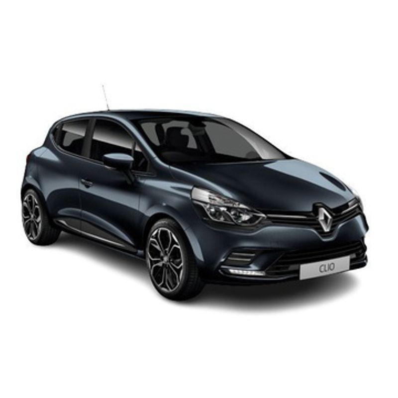
A blinking immobilizer light paired with a dead Stop & Start system is enough to ruin any technician's morning. Modern subcompacts pack executive-level electronics into incredibly tight chassis spaces. On the 2016-2019 Clio IV, the electrical distribution relies heavily on decentralized modules communicating over a high-speed CAN network.
In a busy workshop environment, jumping straight to a scanner often leads you down a rabbit hole of U-codes. You'll frequently see a perfectly good starter motor swapped out because the technician didn't realize the Energy Management Computer was actively inhibiting the starting circuit due to a voltage drop. Utilizing these factory electrical schematics, you shift from guessing to systematic circuit-level analysis, allowing you to prove a component is bad before you order the replacement.
The 1.5L dCi (K9K) is an incredibly robust engine mechanically, but its electronic management requires precise voltage thresholds. This digital workshop reference isolates the specific engine check systems that commonly cause drivability issues.
If there is one model-specific weak point on this platform, it's the Passenger Compartment Relay and Fuse Board—often referred to by techs as the UCH. This module acts as the brain for the interior, managing everything from the Auto-Dimming Internal Rear-View Mirror to the Front One-Touch Windows.
When a customer complains that the daytime running lights flicker when they use the reversing lights, you aren't looking for a bad bulb. That specific failure pattern almost always points to an earth distribution problem. The extensive ground mapping included in this PDF outlines every single remote earth point in the chassis. Armed with your multimeter, you can perform targeted voltage drop testing across these grounds, instantly revealing the corroded lug that's pulling the CAN bus voltage down.
This technical document skips the fluff and delivers 214 pages of pure, high-resolution circuit data.
We know that when a car is stranded on your lift, you don't have time to wait for shipping or deal with broken download portals. That is why our digital delivery system is built for absolute speed. You can securely settle your cart using PayPal, Google Pay, Apple Pay, or any major Credit Card. The exact moment your payment clears, the system fires a direct download link into your email inbox, while simultaneously backing it up in your permanent customer account.
Your diagnostic file remains fully accessible for 10 days (or up to 10 unique downloads), giving you plenty of time to save the 214-page PDF to your shop laptop, tablet, or mobile phone. Furthermore, if your shop's hard drive crashes six months from now, just message us—we provide emergency backup file retrieval via Dropbox so you never lose your investment. Need a visual walkthrough on pulling your files? Watch our quick technician guide here: https://servicemanuals.info/How-to-Download.mp4.
Does this resource cover the specific wiring for the 1.5L 74HP engine variant?
Yes. The engine check and electronic injection sections are specifically mapped for the K9K 1.5L dCi powertrains covering the 55kW-74HP output ranges. The pre-heating and fuel pump relay circuits are exact for this specification.
How do I use these diagrams to fix a Clio that won't lock its doors?
You can cross-reference the "Door Locking" and "Tailgate Locking" circuits with the Passenger Compartment Relay Board diagrams. Often, an internal relay fails inside the UCH. The pinout guide allows you to manually jump the actuator circuit at the connector to verify if the latch mechanism is good before condemning the entire control unit.
Are the CAN-bus communication lines explicitly detailed?
Absolutely. There is a dedicated "CAN Network" section. It illustrates the twisted-pair wiring connecting the steering angle sensor, ABS module, and main instrument panel, which is crucial for troubleshooting directional stability control errors.
Is it easy to read the wire color codes on a mobile device?
The PDF is generated using native vector graphics. This means you can pinch and zoom extensively on your phone's screen to read tiny wire color abbreviations and terminal block numbers without the image becoming pixelated.
Download the complete workshop manual PDF instantly and perform repairs with confidence.