- -$10.00
- New
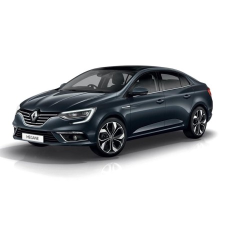


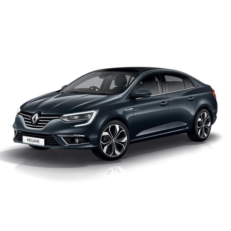
Working on modern French electrical architectures requires a fundamental shift in how you approach the bay. You can't just chase a wire from a switch to a bulb anymore. The 2016-2024 Renault Megane heavily relies on the Passenger Compartment Computer (often known as the UCH) to translate analog inputs into digital CAN network requests.
When a customer complains that the "Keyless Vehicle and Hands-Free Access" only works intermittently on the driver's side, throwing a new door handle at the car is a risky gamble. In real-world repair scenarios, that symptom frequently points to a degraded connection at one of the internal aerials. By accessing these factory electrical schematics, you can map the signal failure straight back to the UCH. Doing a simple continuity check on the exact pins specified in the connector details prevents you from wasting hundreds of dollars on unneeded transponder parts.
The 1.6L diesel powerplant is mechanically solid, but its emission control network is incredibly sensitive to voltage fluctuations. When the Injection Computer detects implausible data, it immediately restricts engine performance.
Instead of guessing which sensor is pulling the 5-volt reference line down, you can use this technical document to analyze the circuit-level impact. The archive includes highly specific pinout references for critical powertrain components:
One observation any seasoned technician will share about the Megane platform is its susceptibility to earth distribution failures. A slightly corroded ground lug can cause the Electronic Parking Brake Control unit to lose communication with the Anti-Lock Braking System.
To combat this, the provided schematics contain a dedicated section mapping every major earth point on the chassis. Whether you are hunting down the "Dashboard Left-Hand Cross Member Electrical Earth" or checking the "UCH Electrical Earth," you get the exact physical locations. You can attach your multimeter directly from the module's ground pin to the battery negative, instantly verifying if high resistance is the true cause of your CAN bus communication faults.
This is a professional-grade PDF built for rapid deployment on the shop floor. It is fully searchable, meaning you don't have to flip through pages with greasy fingers.
We realize a stranded car tying up your hoist costs you money by the hour. Getting your diagnostic data needs to be immediate.
Can I use these schematics to test the motorized EGR valve on the RM9 diesel engine?
Absolutely. The archive specifically includes "Connector Details 1460-Motorised Egr Solenoid Valve". You can identify the exact power, ground, and signal wires. This allows you to command the valve with a bi-directional scanner while simultaneously back-probing the connector to ensure the motor is actually receiving the voltage required to move the pintle.
Why is my Megane throwing an electronic parking brake error after a rear brake job?
This is a common module interaction problem. When retracting the calipers, the harness can sometimes get stretched. Look at the "Automatic Parking Brake Electrical Unit" (Connector Details 1217). The diagram will show you the twisted-pair communication lines running back to the ABS module. You can check these lines for an open circuit right at the rear wheels.
How do I track down an instrument panel that intermittently goes completely black?
Start with the earth distribution. The Megane uses specific ground points for cabin electronics. Reference the "Dashboard Cross Member Radio Earth" and the "UCH Electrical Earth" maps. By testing the voltage drop on these specific chassis points while the cluster is acting up, you can quickly determine if the display is losing its ground path before you pull the entire dashboard apart.
Are the pinouts for the Head-Up Display and central screen included?
Yes. You will find dedicated connector views for the "Head-Up Display" (Connector 2400) and the "Multifunction Control Screen" (Connector 2402). This is critical for diagnosing blank screens or lost communication between the infotainment and the main CAN network.