- -$10.00


Battery circuits, protected positive battery connections, power supply fuse boards, unit fuses, passenger compartment fuse boxes, and engine and relay fuse boxes. Relay blocks, command relay blocks, front fog lights relays, fan speed relays, and central door locking timers/control modules.
Starting and charging circuits including alternators, starters, and preheating units. Electronic injection computers, injectors (1 through 4), fuel pumps, fuel pump relays, diesel pumps, and injection locking relays.
Engine sensors and actuators covering pinking sensors, atmospheric pressure sensors, TDC sensors, throttle potentiometers, upstream and downstream oxygen sensors, oil level sensors, water injection temperature sensors, coolant dual function temperature switches, injection air temperature sensors, engine speed sensors, and throttle bodies. Ignition systems featuring quadruple ignition coil modules and individual ignition coils for cylinders 1 to 4.
Anti-lock braking system (ABS) computers, front and rear wheel speed sensors, and ABS connection harnesses. Braking and steering control components including brake switches, handbrake switches, brake fluid minimum level sensors, and power assisted steering pressure switches.
Headlight schematics covering right and left headlights, headlight adjustment controls, headlight corrector motors, front foglights, and front fog light relays. Signalling and warning circuits including turn signal lights, side repeaters, rear lights, raised brake lights, reversing lights switches, and tailgate registration plate lighting.
Visibility and wiper wiring featuring windscreen wiper motors, rear screen wiper motors, windscreen washer pumps, combined wiper-washers, and monolevers. Audible and control devices including main electromagnetic horns, cigarette lighters, hazard warning light controls, flasher units, and lights on warning buzzers / driving school alarms.
Heating control panels, air conditioning control panels, air conditioning clutches, pressure switches, and tri-function pressure switches. Air conditioning fan assemblies, base fan assemblies, fan assembly resistors, cold air blower relays, fan speed 2 relays, and cooling fan units.
Central door locking controls, door locking timers, boot lid electric locking, and electric locking mechanisms for driver, passenger, and rear doors. Electric window controls and motors for driver and passenger sides, plus electric rear-view mirror controls and adjustment motors.
Interior comfort wiring covering heated rear window controls, rear screen de-icing, luggage compartment lighting, front courtesy lights, and door/boot rabbet switches.
Audio systems featuring radios, front door speakers, rear speakers, and right-hand tweeter speakers. Display and diagnostic connectors including digital/analogue clocks, clock/external temperature/carphone display assemblies, and diagnostic sockets. Auxiliary components including petrol vapour absorbers and right-hand rear seat controls.
Air bag and seat belt pretensioner computers, driver and passenger pretensioners, driver and passenger side air bags, passenger air bags, and driver/passenger side satellites. Security and immobiliser components including decoder computers, cruise control and air bag switches, and impact (inertia) sensors.
Interface and wiring connection points covering engine-to-engine connections, side member/headlight connections, passenger compartment connections to doors, tailgate, ABS, courtesy lights, bumpers, pretensioners, and radio displays. Engine/passenger compartment single unit connections, dashboard/alarm connections, and ABS-to-ABS connections.
Complete electrical earth distribution layouts covering front right/left-hand earths, ABS earth, rear right-hand earth, engine electrical earth, right/left-hand A-pillar earths, climate system ducts earth, and radio electrical earth.
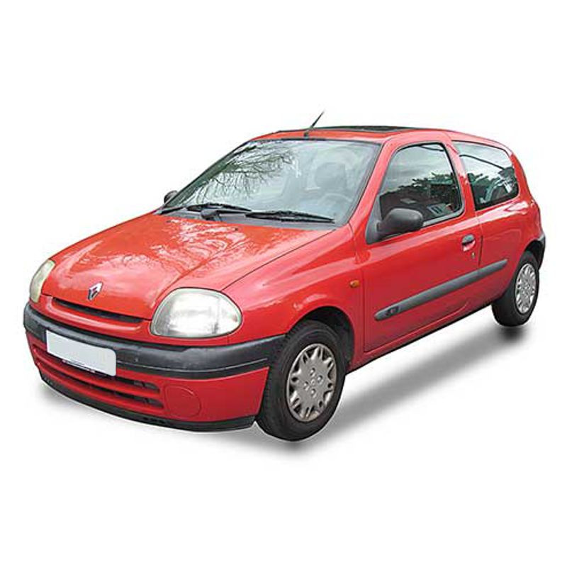
A familiar scenario for any technician working on European cars: A Phase 1 Clio is towed in. The starter motor cranks beautifully, but the red immobilizer dot flashes rapidly on the instrument panel. Far too often, mechanics will immediately order an expensive new key and lockset, or send the 120 Injection Computer out to a third-party for an immobilizer bypass.
During practical troubleshooting, your first move should actually be checking the continuity between the transponder ring and the 503 Decoder Computer. Using this specific technical document, you can identify the precise wire routing that passes through the R212 (Engine/Passenger Compartment Single Unit) connection. Quite frequently, moisture ingress at this specific junction drops the 5-volt reference, killing fuel injection entirely. Probing these pins correctly saves the customer hundreds of dollars and prevents unnecessary part swapping.
The 1.2L and 1.4L engines found in this generation are notorious for heat-soak issues, specifically failing to start when the engine bay is hot. This workshop reference contains the complete, unedited layouts for critical timing components like the 149 TDC Sensor and the 778 Quadruple Ignition Coil Module.
Instead of guessing if the sensor is outputting an AC voltage signal, you can map the signal return directly to the ECM. Furthermore, if you are working on a diesel variant suffering from fuel starvation, you can trace the 236 Fuel Pump Relay. This ensures the 711 Diesel Pump is receiving full battery voltage, rather than a crippled 9 volts caused by a heavily oxidized MH (Engine Electrical Earth) point.
Renault utilized a heavily modular harness design on the Phase 1 chassis. If the 123 Central Door Locking Control malfunctions, do not just rip off the door card to replace the 140 Driver's Door electric locking motor. The issue is almost always a broken wire in the door jamb conduit. By looking up the R153 (Passenger Compartment/Driver's Door Connection) and R154 block diagrams, you can test the lock actuator inputs right from the kick panel. This resource maps every single "R" connection, including the critical R183 Anti-Lock Braking System connection, allowing you to test wheel speed sensors (150-153) without crawling under the chassis.
Unlike a flat, scanned paper manual, this factory data is packaged as a highly responsive HTML interface. After extracting the 17 MB ZIP file on your computer, it opens directly in Chrome, Firefox, or Edge. You can seamlessly click through menus in English, Deutsch, Français, and Russian to locate exactly which circuit you need.
Get immediate access to the full service manual and start diagnosing with precision. Eliminate the dangerous guesswork involved in multiplexed wiring repairs today.
We know the frustration of having a dead bay tied up by an electrical gremlin. Your access to this data is instantaneous.
Why do my Clio's left and right indicator lights flash rapidly when I press the brake pedal?
This "disco effect" is a legendary Renault fault, almost always caused by a failing ground plane at the taillight clusters. Current backfeeds through the turn signal bulbs seeking a path to ground. You can utilize these schematics to pinpoint the MF (Rear Right-Hand Earth) or ME (Body Electrical Relay) points and measure the exact voltage drop across the 172 and 173 Rear Light circuits.
I am chasing a hot-start issue. Are the crankshaft position sensor wires clearly mapped?
Absolutely. The diagrams explicitly detail the routing for the 149 TDC (Top Dead Center) Sensor. This allows you to verify the resistance and AC signal return lines directly at the 120 Injection Computer harness connector, ruling out a broken wire before buying a new sensor.
Does this cover the central locking timer module? My doors keep locking and unlocking randomly.
Yes. The 264 Central Door Locking Timer and the 123 Central Door Locking Control are fully documented. You can easily trace the inputs from the 154 Tailgate Switch or the individual door rabbet switches (178-181) to see which sensor is sending a false "open" signal to the timer.
What software do I actually need to navigate this specific file type?
No specialized automotive software or PDF reader is required. The download arrives as a standard 17 MB compressed ZIP file. Once you extract the folder to your desktop, simply double-click the main index file to open the interactive, offline wiring interface in any standard web browser.