• -$10.00
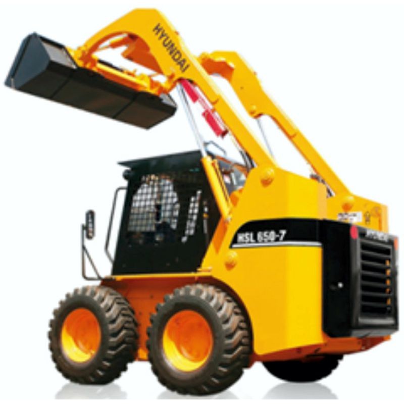
Hyundai Skid Steer Loader HSL650-7 - Service Manual - Operators - Wiring Diagrams
search
  • Hyundai Skid Steer Loader HSL650-7 - Service Manual - Operators - Wiring Diagrams

Hyundai Skid Steer Loader HSL650-7 - Service Manual - Operators - Wiring Diagrams

$29.95
$19.95 Save $10.00
No tax
Quantity

YOUTUBE Official Channel @SoloPDFcom (+18,000 subs). Trusted by mechanics worldwide using professional workshop manuals and wiring diagrams.

Hyundai Skid Steer Loader HSL650-7 - Service Manual - Operators - Wiring Diagrams

Digital technical documentation with sections on SECTION 1, Group 1 Safety Hints, Group 2 Specifications. Review the complete contents below for the systems and procedures covered.

Manual contents

  • SERVICE MANUAL
  • - SECTION 1
  • - GENERAL
  • - Group 1 Safety Hints
  • - Group 2 Specifications
  • - Group 3 Maintenance
  • - SECTION 2
  • - HYDRAULIC SYSTEMUNCTION
  • - Group 1 Hydraulic circuit
  • - Group 2 Hydraulic component testing
  • - Group 3 Self level valve(Option)
  • - Group 4 Auxiliary pump
  • - Group 5 Main pump
  • - Group 6 Travel motor
  • - Group 7 Main control valve
  • - Group 8 Boom and bucket cylinder
  • - SECTION 3
  • - ELECTRICAL SYSTEM
  • - Group 1 Component location
  • - Group 2 Wiring diagram
  • - Group 3 Electrical component specification
  • - Group 4 Connector destination
  • - SECTION 4
  • - POWER TRAIN
  • - Group 1 Power train component
  • - Group 2 Front and rear axle
  • - SECTION 5
  • - CONTROL
  • - Group 1 Hand control
  • - Group 2 Parking brake
  • - Group 3 Attachment holder
  • - SECTION 6
  • - TROUBLE SHOOTING
  • - Group 1 Travel hydraulics
  • - Group 2 Boom and bucket hydraulic
  • - Group 3 Power train
  • - Group 4 Control
  • - Group 5 Electrical system
  • ENGINE SERVICE MANUAL
  • - 1. ENGINE IDENTIFICATION
  • - [1] Model Name And Engine Serial Number
  • - [2] E2b Engine
  • - [3] Cylinder Number
  • - 2. GENERAL PRECAUTION
  • - 3. MAINTENANCE CHECK LIST
  • - 4. CHECK AND MAINTENANCE
  • - [1] Dialy Check Points
  • - [2] Check Points Of Every 50 Hours
  • - [3] Check Points Of Every 100 Hours
  • - [4] Check Points Of Every 150 Hours
  • - [5] Check Points Of Every 200 Hours
  • - [6] Check Points Of Every 300 Hours
  • - [7] Check Points Of Every 400 Hours
  • - [8] Check Points Of Every 500 Hours
  • - [9] Check Points Of Every 1 Or 2 Months
  • - [10] Check Points Of Every Year
  • - [11] Check Points Of Every 800 Hours
  • - [12] Check Points Of Every 1500 Hours
  • - [13] Check Points Of Every 2years
  • - 5. SPECIAL TOOLS
  • - 1. ENGINE BODY
  • - [1] Piston
  • - [2] Built-In Dynamic Balancer (Balancer Model Only)
  • - [3] Half-Floating Head Cover
  • - 2. COOLING SYSTEM
  • - [1] Bottom Bypass System
  • - 3. FUEL SYSTEM
  • - [1] Governor
  • - 4. ELECTRICAL SYSTEM
  • - [1] Starter Auto Reduction Unit
  • - 5. TURBOCHARGER SYSTEM
  • - [1] Boost Compensator
  • - 1. TROUBLESHOOTING
  • - 2. SERVICING SPECIFICATIONS
  • - 3. TIGHITENING TORQUES
  • - [1] Tightening Torques For General Use Screws, Bolt And Nuts
  • - [2] Tightening Torques For Special Use Screws, Bolt And Nuts
  • - 4. CHECKING, DISASSEMBLING AND SERVICING
  • - [1] Checking And Adjusting
  • - (1) Engine body
  • - (2) Lubricating system
  • - (3) Cooling system
  • - (4) Fuel system
  • - (5) Electrical system
  • - (6) Turbocharger
  • - [2] Diassembling And Assembling
  • - (1) Draining coolant and Oil
  • - (2) External Components
  • - (3) Cylinder Head and Valves
  • - (4) Timing Gears, Camshaft and fuel Camshaft
  • - (5) Piston and Connecting Rod
  • - (6) Crankshaft
  • - (7) Thermostat and Water Pump
  • - (8) Starter
  • - (9) Alternator
  • - (10) Turbocharger
  • - [3] Servicing
  • - (1) Cylinder Head and Valves
  • - (2) Timing Gears, Camshaft and fuel Camshaft
  • - (3) Piston and Connecting Rod
  • - (4) Crankshaft
  • - (5) Cylinder
  • - (6) Oil Pump
  • - (7) Starter
  • - (8) Alternator
  • - (9) Wiring Diagram
  • OPERATORS MANUAL
  • - Foreword
  • - Section 1
  • - Safety hints
  • - Section 2
  • - Specifications
  • - Section 3
  • - Control devices
  • - Section 4
  • - Operation
  • - Section 5
  • - Transportation
  • - Section 6
  • - Maintenance
  • - Section 7
  • - Troubleshooting