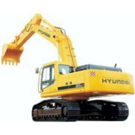
Hyundai Crawler Excavator RC215C-7 - Service Repair Manual - Wiring Diagrams
Digital technical documentation with sections on CRAWLER TYPE EXCAVATOR [RC215C-7], FOREWORD, SECTION 1. Review the complete contents below for the systems and procedures covered.
Manual contents
- SERVICE MANUAL
- - CRAWLER TYPE EXCAVATOR [RC215C-7]
- - FOREWORD
- - SECTION 1
- - GENERAL
- - Group 1 Safety Hints
- - Group 2 Specifications
- - SECTION 2
- - STRUCTURE AND FUNCTION
- - Group 1 Pump Device
- - Group 2 Main Control Valve
- - Group 3 Swing Device
- - Group 4 Travel Device
- - Group 5 RCV Lever
- - Group 6 RCV Pedal
- - SECTION 3
- - HYDRAULIC SYSTEM
- - Group 1 Hydraulic Circuit
- - Group 2 Main Circuit
- - Group 3 Pilot Circuit
- - Group 4 Single Operation
- - Group 5 Combined Operation
- - SECTION 4
- - ELECTRICAL SYSTEM
- - Group 1 Component Location
- - Group 2 Electrical Circuit
- - Group 3 Monitoring System
- - Group 4 Electrical Component Specification
- - Group 5 Connectors
- - SECTION 5
- - Group 1 Outline
- - Group 2 Operation of CAPO system
- - Group 3 System diagram
- - Group 4 Engine control system
- - Group 5 EPPR valve
- - Group 6 Prolix switch
- - Group 7 Function and elec circuit
- - SECTION 6
- - TROUBLESHOOTING
- - Group 1 Hydraulic and Mechanical System
- - Group 2 Electrical System
- - Group 3 Mechatronics System
- - SECTION 7
- - MAINTENANCE STANDARD
- - Group 1 Operational Performance Test
- - Group 2 Major Components
- - Group 3 Track and Work Equipment
- - SECTION 8
- - DISASSEMBLY AND ASSEMBLY
- - Group 1 Precaution
- - Group 2 Tightening Torque
- - Group 3 Pump Device
- - Group 4 Main Control Valve
- - Group 5 Swing Device
- - Group 6 Travel Device
- - Group 7 RCV Lever
- - Group 8 Turning Joint
- - Group 9 Boom, Arm and Bucket Cylinder
- - Group 10 Undercarriage
- - Group 11 Work Equipment
- ENGINE SERVICE MANUAL
- - Introduction
- - Engnee Identification
- - Engine Disassembly and Assembly
- - Cylinder Block
- - Cylinder Head
- - Rocker Levers
- - Cam Follower
- - Fuel System
- - lnjectors and Fuel Lines
- - Lubricating System
- - Cooling System
- - Drive Units
- - Air Intake System
- - Exhaust System
- - Air Equipment
- - Electrical Equipment
- - Engine Testing
- - Mounting Adaptations
- - Specifications
- - Service Literature
- - Component Manu1acturersvNames and Addresses
- - Index