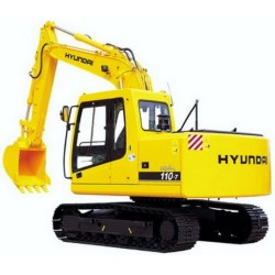
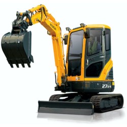
Hyundai Mini Excavator R28-7 - Service Manual - Operators - Wiring Diagrams
Digital technical documentation with sections on Precautions on Maintenance, Outline, Attachment. Review the complete contents below for the systems and procedures covered.
Manual contents
- SERVICE MANUAL
- - Precautions on Maintenance
- - Outline
- - Attachment
- - Engine
- - Main Pump
- - Hydraulic Oil Filter
- - Control Valve
- - Joystick
- - Slew Motor
- - Travel Motor
- - Hydraulic Cylinder
- - Swivel Joint
- - Crawler
- - Spring Case and Grease Cylinder
- - Idler
- - Sprocket
- - Track Roller
- - Electrical Equipment
- - Troubleshooting
- ENGINE SERVICE MANUAL
- - INTRODUCTION
- - HOW TO USE THIS MANUAL
- - TABLE OF CONTENTS
- - 1 MODEL IDENTIFICATION AND SERIAL NUMBER LOCATION
- - 1.1 Model identification location
- - 1.2 Serial Number Location
- - 2 COMPONENT LOCATION
- - 2.1 S3L/S3L2
- - 2.2 Engine S3L-T/S3L2-T
- - 2.3 S4L/S4L2
- - 2.4 Engine S4L-T/S4L2-T
- - 3 SPECIFICATIONS
- - 4 DETERMINING WHEN TO OVERHAUL THE ENGINE
- - 5 COMPRESSION PRESSURE MEASUREMENT
- - 5.1 Inspection
- - 5.2 Measurement
- - 6 TROUBLESHOOTING
- - 6.1 General
- - 6.2 Engine troubleshooting
- - 6.3 Starting system troubleshooting
- - 7 BASIC PRECAUTIONS FOR DISASSEMBLY AND ASSEMBLY
- - 7.1 Disassembly
- - 7.2 Assembly
- - 8 PREPARATION FOR DISASSEMBLY
- - 8.1 Engine oil draining
- - 8.2 Coolant draining 1
- - 9 ELECTRICAL SYSTEM
- - 9.1 Starter
- - 9.2 Alternator
- - 10 Cooling System
- - 10.1 Cooling fan removal
- - 10.2 Thermostat case removal
- - 10.3 Water pump assembly removal
- - 11 Fuel System
- - 11.1 Fuel injection pipe removal
- - 11.2 Fuel injection nozzle removal
- - 11.3 Governor assembly removal
- - 11.4 Governor weight removal
- - 11.5 Fuel injection pump removal
- - 12 Lubrication System
- - 12.1 Oil filter removal
- - 12.2 Pressure relief valve removal
- - 12.3 Oil pressure switch removal
- - 13 AIR INLET SYSTEM AND EXHAUST SYSTEM
- - 13.1 Exhaust manifold removal
- - 13.2 Air inlet cover removal
- - 14 CYLINDER HEAD AND VALVE MECHANISM
- - 14.1 Rocker shaft assembly removal
- - 14.2 Rocker shaft disassembly
- - 14.3 Cylinder head bolt removal
- - 14.4 Cylinder head assembly removal
- - 14.5 Valve and valve spring removal
- - 14.6 Valve stem seal removal
- - 15 Timing Gears and Flywheel
- - 15.1 Flywheel removal
- - 15.2 Rear plate removal
- - 15.3 Oil seal case removal
- - 15.4 Tappet removal
- - 15.5 Speedometer driven gear removal
- - 15.6 Crankshaft pulley removal
- - 15.7 Timing gear case removal
- - 15.8 Timing gear backlash measurement
- - 15.9 Idler gear removal
- - 15.10 Camshaft removal
- - 15.11 Fuel injection pump camshaft removal
- - 15.12 Gear removal (when required)
- - 15.13 Oil pump removal
- - 15.14 Front plate removal
- - 16 Cylinder Block, Crankshaft, Pistons and Oil Pan
- - 16.1 Oil pan removal
- - 16.2 Oil screen removal
- - 16.3 Thrust clearance measurement for connecting rod big end
- - 16.4 Connecting rod cap removal
- - 16.5 Piston removal
- - 16.6 End play measurement for crankshaft
- - 16.7 Main bearing cap removal
- - 16.8 Crankshaft removal
- - 16.9 Piston separation from connecting rod
- - 17 CYLINDER HEAD AND VALVE MECHANISM
- - 17.1 Cylinder head
- - 17.2 Rocker arms and rocker shaft
- - 17.3 Valve springs
- - 17.4 Valve push rods
- - 17.5 Valves, valve guides and valve seats
- - 17.6 Combustion jet replacement
- - 18 TIMING GEARS AND FLYWHEEL
- - 18.1 Camshaft
- - 18.2 Fuel injection pump camshaft
- - 18.3 Tappets
- - 18.4 Idler gear
- - 18.5 Flywheel and ring gear
- - 19 CYLINDER BLOCK, CRANKSHAFT, PISTONS AND OIL PAN
- - 19.1 Pistons, Piston Rings and Piston Pins
- - 19.2 Connecting rods
- - 19.3 Crankshaft
- - 19.4 Cylinder block
- - 20 Cylinder Block, Crankshaft, Pistons and Oil pan
- - 20.1 Main bearing installation
- - 20.2 Crankshaft installation
- - 20.3 Main bearing cap installation
- - 20.4 Side seal installation
- - 20.5 Piston assembling-connecting rod
- - 20.6 Piston ring installation
- - 20.7 Piston and connecting rod installation
- - 20.8 Connecting rod cap installation
- - 20.9 Oil screen installation
- - 20.10 Oil pan installation
- - 21 Timing Gears and Flywheel
- - 21.1 Front plate installation
- - 21.2 Oil pump installation
- - 21.3 Engine turning
- - 21.4 Engine turning
- - 21.5 Camshaft installation
- - 21.6 Idler gear installation
- - 21.7 Timing gear case installation
- - 21.8 Crankshaft pulley nut tightening
- - 21.9 P.T.O. gear installation
- - 21.10 Speedometer driven gear installation
- - 21.11 Tappet installation
- - 21.12 Oil seal case installation
- - 21.13 Rear plate installation
- - 21.14 Flywheel installation
- - 22 CYLINDER HEAD AND VALVE MECHANISM
- - 22.1 Cylinder head bottom face cleaning
- - 22.2 Valve stem seal installation
- - 22.3 Valve spring installation
- - 22.4 Installing valve block
- - 22.5 Cylinder head gasket installation
- - 22.6 Cylinder head installation
- - 22.7 Cylinder head bolt tightening
- - 22.8 Valve push rod installation
- - 22.9 Rocker shaft assembling
- - 22.10 Rocker shaft assembly installation
- - 22.11 Valve clearance adjustment
- - 22.12 Rocker cover installation
- - 23 Air Inlet System and Exhaust System
- - 23.1 Air inlet cover installation
- - 23.2 Exhaust manifold installation
- - 24 Fuel System
- - 24.1 Fuel injection nozzle installation
- - 24.2 Fuel injection pump installation
- - 24.3 Flyweight assembly installation
- - 24.4 Sliding sleeve installation
- - 24.5 Governor assembly installation
- - 24.6 Fuel injection line installation
- - 25 Lubrication system
- - 25.1 Pressure relief valve installation
- - 25.2 Oil filter installation
- - 25.3 Oil pressure switch installation
- - 26 Cooling system
- - 26.1 Water pump installation
- - 26.2 Thermostat installation
- - 26.3 Cooling fan installation
- - 26.4 Thermoswitch and thermounit combination installation
- - 27 Electrical System
- - 27.1 Glow plug installation
- - 27.2 Alternator installation
- - 28 GENERAL
- - 28.1 Specifications (standard)
- - 28.2 Wiring diagrams
- - 29 STARTER
- - 29.1 Disassembly
- - 29.2 Inspection
- - 29.3 Assembly
- - 29.4 Inspection and Testing after Assembly
- - 30 ALTERNATOR
- - 30.1 Disassembly
- - 30.2 Inspection
- - 30.3 Assembly
- - 31 KEY SHUTOFF SYSTEM (ETS solenoid type)
- - 31.1 General
- - 31.2 Cord color (standard)
- - 31.3 Shutoff solenoid installation
- - 31.4 Inspection after assembly
- - 32 KEY SHUTOFF SYSTEM (ETR solenoid type)
- - 32.1 General
- - 32.2 Cord color (standard)
- - 32.3 Shutoff solenoid installation
- - 33 AUTOMATIC GLOW SYSTEM
- - 33.1 General
- - 33.2 Glow timer specification (standard)
- - 33.3 Glow plug relay specifications (standard)
- - 33.4 Glow plug inspection
- - 34 GENERAL
- - 34.1 Schematic
- - 34.2 Specifications (standard)
- - 35 INSPECTION
- - 35.1 Water pump
- - 35.2 Thermostat (standard)
- - 35.3 Thermoswitch (standard)
- - 35.4 Thermounit (standard)
- - 36 GENERAL
- - 36.1 Schematic
- - 36.2 Specifications
- - 37 INSPECTION
- - 37.1 Oil pump
- - 37.2 Oil pressure switch
- - 37.3 Pressure relief valve
- - 38 GENERAL
- - 38.1 Schematic
- - 38.2 Specifications (standard)
- - 39 FUEL INJECTION NOZZLE
- - 39.1 Inspection
- - 39.2 Disassembly and assembly
- - 40 FUEL INJECTION PUMP
- - 40.1 Test on engine
- - 40.2 Disassembly
- - 40.3 Inspection
- - 40.4 Assembly
- - 41 GOVERNOR
- - 41.1 Disassembly and inspection
- - 41.2 Assembly
- - 41.3 Torque spring set installation
- - 42 FUEL PUMP
- - 42.1 Inspection
- - 43 FUEL FILTER
- - 44 GENERAL
- - 44.1 Schematic
- - 45 INSPECTION
- - 45.1 Inspection procedure
- - 46 LUBRICATION AND MAINTENANCE CHART
- - 47 ENGINE OIL AND OIL FILTER
- - 47.1 Engine oil specifications
- - 47.2 Oil level check
- - 47.3 Oil and oil filter change
- - 47.4 Oil filter change
- - 48 VALVE CLEARANCE
- - 49 FUEL INJECTION TIMING
- - 49.1 Preparation
- - 49.3 Adjustment
- - 50 FUEL FILTER
- - 50.1 Fuel filter with [AIR] valve
- - 50.2 Cartridge (air vent screw) type fuel filter
- - 51 FUEL SYSTEM PRIMING
- - 51.1 Engine with fuel filter with [AIR] valve
- - 51.2 Engine with cartridge (air vent screw) type fuel filter
- - 52 IDLE RPM SETTING
- - 53 FUEL INJECTION NOZZLES
- - 53.1 Injection pressure (valve opening pressure) test
- - 53.2 Orifice restriction test
- - 53.3 Nozzle tip washing and replacement
- - 53.4 Installation
- - 54 FAN BELT
- - 55 SPECIFICATIONS
- - 55.1 Basic engine components
- - 55.2 Lubrication system
- - 55.3 Fuel system
- - 55.4 Air inlet system and exhaust system
- - 55.5 Cooling system (standard)
- - 55.6 Electrical system
- - 56 TIGHTENING TORQUES
- - 56.1 Major bolts and nuts
- - 56.2 Torques for bolts and nuts with standard threads
- - 56.3 Torques for plugs with taperlock threads
- - 57 SEALANTS
- - 58 SPECIAL TOOLS
- OPERATORS MANUAL
- - OPERATION
- - Safety Decals 1
- - Basic Precautoins on Safety 3
- - Safety Precautionary Notes before Start 4
- - Safety Precautions during Operation 6
- - Safety Precautions during Inspection and Maintenance 15
- - Safety Post Operational Caution 18
- - Part Names 19
- - Explanation of Each Device 21
- - Operation 28
- - Operational Precautions 32
- - Transporting by Truck 39
- - Machine Traction 41
- - How-Hoist a Machine 42
- - Cold Weather or During-Winter Operations 44
- - Long-Period Storage 46
- - INSPECTION AND MAINTENANCE
- - Ordering Parts and Servicing Guidelines 47
- - Inspections 48
- - Maintenance after the First 50 Service Hours (New Machine) 53
- - Maintenance after the First 100 Service Hours (New Machine) 54
- - Maintenance Every 50 Service Hours 55
- - Maintenance Every 100 Service Hours 57
- - Maintenance Every 250 Service Hours 58
- - Maintenance Every 500 Service Hours 59
- - Maintenance Every 1000 Service Hours 61
- - To Pressurize 62
- - Inspection and Maintenance Procedures for Engine Parts 64
- - Inspection and Maintenance Procedures 65
- - Periodical Inspections and Maintenance List 69
- - Lubricants 71
- - OTHERS
- - Dimensions and Specifications 75
- - Hydraulic Circuit 77
- - Electric Circuit 78