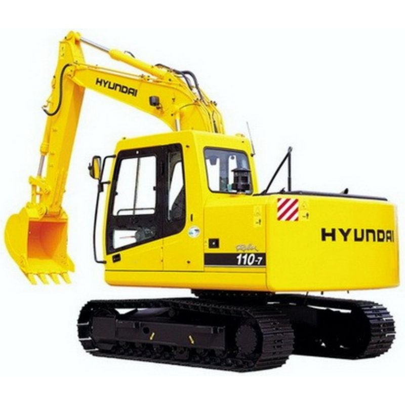
- -$10.00


Let's start with a common shop scenario. You've got an R110-7 throwing fits during combined operations—maybe the boom hoist slows down drastically when you swing the cab. One frequent diagnostic mistake is misdiagnosing electrical faults caused by mechanical issues. A technician might spend hours testing the mode selection system's electrical circuit, unaware that mechanical wear inside the turning joint or a sticking spool in the main control valve is actually creating the massive pressure drop.
This workshop reference gives you the exact hydraulic circuit paths (Main and Pilot) side-by-side with the Mechatronics logic. You can effectively test the engine control system, verify sensor feedback, and check fuse box layouts without throwing expensive, unneeded parts at the machine.
Unlike older, purely mechanical iron, the Hyundai R110-7 utilizes a dedicated Mechatronics System that actively bridges engine performance and hydraulic demand. This network governs the travel speed control, the automatic warming up function, and the engine overheat prevention function.
When something goes wrong, the self-diagnostic system is your first line of defense, but only if you know how to interpret the monitoring system outputs. A common issue technicians encounter is a sensor failure caused by mechanical wear—for example, severe vibration from a neglected undercarriage or a heavy hydraulic breaker attachment can loosen an engine ground strap, which cascades into an erratic monitor display or ECU misinterpretation. This documentation provides the test parameters to isolate the root cause safely.
With 835 pages covering the base machine, the powerplant, and operator protocols, this PDF is exceptionally detailed.
High-pressure hydraulic systems require precise handling during any repair. Bolting up a main control valve without the exact torque specifications can easily warp the internal spool bore, leading to internal bypass leakage that ruins fine grading control.
In many real-world repair cases, relying on generic tightening sequences instead of factory guidelines guarantees a comeback. Having the exact component mounting torque—broken down by engine, electric system, hydraulic system, and structural components—prevents these self-inflicted wounds. Ultimately, this manual protects your timeline, ensuring you get the diagnosis right the first time, whether you are recalibrating the travel device or overhauling the air inlet and exhaust system.
No more greasy thumbprints ruining your only wiring diagram. This PDF is built for the modern bay. It is fully searchable, meaning you can quickly jump from the hydraulic breaker maintenance chart straight to the undercarriage disassembly sequence. Wiring circuits and complex schematics can be zoomed in on a tablet or laptop to trace tricky CAN-bus communication lines right inside the cab.
Downtime costs money, so we skip the shipping delays entirely.
Get immediate access to the full service manual and start diagnosing with precision.
My excavator's auto warm-up function isn't kicking on in cold weather. Will this help me trace the issue?
Yes. Section 5 details the specific mechatronics logic behind the automatic warming up function. You can use the electrical circuit layouts to test the coolant temperature sensors and verify if the controller is receiving the correct resistance values, or if there's simply a broken wire in the harness.
Does this technical document include instructions for rebuilding the main hydraulic pump?
It does. You will find complete disassembly and assembly procedures for the main pump device (Section 8, Group 3), including the required special tools, specific tightening torques, and operational performance tests to verify your rebuild before putting the machine back in the dirt.
Can I use this guide to figure out why my travel speed control is stuck in low gear?
Absolutely. Travel speed control relies on a mix of electrical solenoid activation and pilot hydraulic pressure. The manual allows you to diagnose the Mechatronics travel speed control system electrically, while also providing the mechanical teardown steps for the travel device if the issue is a stuck mechanical spool.
Are the specific settings for adding a hydraulic breaker attachment included?
Yes, the Operators Manual section contains a dedicated Hydraulic Breaker chapter (Section 8). It covers the necessary circuit configuration, selecting the right breaker weight class, operating precautions, and maintenance for the quick clamp system.