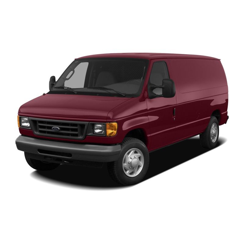
- -$10.00


Nobody wants to pull the doghouse cover off a heavily loaded E-350 just to hunt for a frayed wire. When an Econoline comes into the bay with erratic instrument cluster behavior or a crank-no-start condition, finding the root cause requires exact structural blueprints. During the 2003 to 2007 window, Ford offered incredibly diverse configurations for this platform. A technician might look at a 5.4L CNG (Compressed Natural Gas) delivery step-van in the morning, and a 6.0L Diesel ambulance cutaway in the afternoon.
Without the specific schematics detailing how the wiring branches off into Auxiliary Relay Box 1 or 2, you are simply guessing. This PDF document breaks down the electrical system year by year, engine by engine, and chassis by chassis, so you can perform accurate voltage drop testing and get the truck back on its route.
The engine performance and drivetrain circuits on these workhorses are highly specialized. A major weak point on the 6.0L Power Stroke diesel, for instance, involves harness chafing near the Fuel Injection Control Module (FICM) and the sensors located at the rear of the block. By referencing the dedicated 6.0L Diesel Engine Performance sections, you can verify sensor inputs to the ECU before replacing expensive hardware.
Furthermore, transmission electronics underwent major updates during these years. The factory electrical schematics completely map out the shift interlock and solenoid control circuits for the older 4R100, the 4R70E/4R75E, and the heavy-duty TorqShift gearboxes. If a truck goes into fail-safe mode, you can immediately check the data lines running between the transmission range sensor and the powertrain control module.
In practical diagnostics, upfitted vehicles present the biggest headaches. Ford built thousands of these as Cutaway or Stripped Chassis units, destined to become RVs, box trucks, and emergency vehicles.
Consequently, their electrical routing for anti-lock brakes, exterior lamps, and ground distribution is completely different from a standard cargo van. This technical document explicitly divides systems by "W/ Stripped Chassis" and "W/O Stripped Chassis". It shows exactly where the factory ground distribution circuits terminate on the bare frame rails, preventing you from confusing a Ford factory ground issue with a faulty aftermarket upfitter installation.
Having the circuit diagram is only step one; knowing where the splice pack lives in a cramped Econoline cab is step two. The comprehensive Component Locators section in this file is a massive time-saver.
It provides detailed visual maps for the Battery Junction Box (BJB), left and right A/B pillars, the floor pan routing, and both the front and rear HVAC setups. If you need to test a power door lock actuator on a sliding side door versus a hinged side door, the locators point you right to the correct harness disconnect.
Waiting days for a printed manual to arrive while a commercial client complains about downtime is bad for business. That is why we provide instant access wiring diagrams. Check out securely utilizing Google Pay, Apple Pay, PayPal, or any major Credit Card.
Immediately after purchase, a download link for the EWD manual PDF is deposited in your email and active within your customer account. You get 10 downloads valid for 10 days, making it easy to store the 498-page file on your shop PC, your diagnostic Toughbook, and your mobile device. If your shop's network blocks the automated download, we back every order with a secure Dropbox delivery upon request. Stop fighting phantom voltage drops and grab the exact blueprints today.
How does this handle the wiring differences between a standard passenger van and a commercial Cutaway chassis?
The document explicitly splits major circuits—like exterior lighting, ABS, wiper/washers, and ground distribution—into separate diagrams for "W/ Stripped Chassis," "Cutaway Chassis," and standard body configurations. This ensures you are looking at the exact wire routing for the specific vehicle in your bay.
My fleet runs 2006 6.0L diesels with dual alternators; are those charging circuits detailed?
Yes. High-amp commercial setups are fully covered. The starting and charging chapters provide specific factory electrical schematics for the 7.3L DI Turbo Diesel and 6.0L Diesel equipped "W/ Dual Generators" as well as standard single generator setups.
Can I use these factory electrical schematics to track down a TorqShift transmission shifting issue?
Absolutely. The transmission sections (A/T Circuits) detail the exact pinout reference guide for the TorqShift gearboxes, completely separate from the 4R100 and 4R75E diagrams, allowing you to trace solenoid commands and shift interlock faults accurately.
Is the compressed natural gas (CNG) 5.4L engine performance wiring included?
It is. Given their popularity in municipal fleets, the 5.4L CNG/NGV variants have their own dedicated engine performance, starting, charging, and cruise control circuit diagrams for the years they were offered.