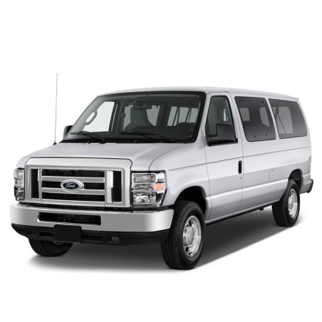
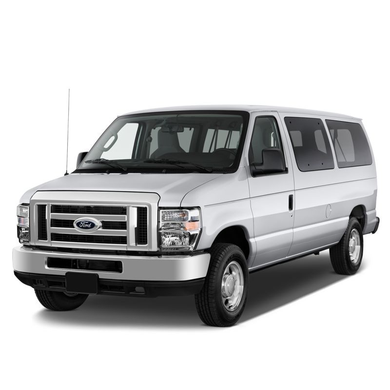
Ford E-350 Super Duty (2008-2014) Wiring Diagrams & Component Locations
Electrical circuit, wiring and component-location reference for the model named above. It is not represented as a mechanical workshop or overhaul manual.
Index highlights: OEM WIRING DIAGRAMS E-SERIES; 17: 5.4L, Engine Performance Circuit, W/ Torqshift (1 of 5); 5: Anti-lock Brakes Circuit, W/ Stability Assist (1 of 2).
Languages stated in the original listing: English.
Scope note: Year- and configuration-specific electrical circuits should be selected using the headings in the original index.
Original technical index
- CONTENTS:
- ELECTRICAL WIRING DIAGRAMS
- 2008 Ford Econoline E350 Super Duty
- - 1: Manual A/C Circuit, W/ Stripped Chassis (1 of 2)
- - 2: Manual A/C Circuit, W/ Stripped Chassis (2 of 2)
- - 3: Manual A/C Circuit, W/O Stripped Chassis (1 of 2)
- - 4: Manual A/C Circuit, W/O Stripped Chassis (2 of 2)
- - 5: Anti-lock Brakes Circuit, W/ Stability Assist (1 of 2)
- - 6: Anti-lock Brakes Circuit, W/ Stability Assist (2 of 2)
- - 7: Anti-lock Brakes Circuit, W/O Stability Assist
- - 8: Forced Entry Circuit (1 of 2)
- - 9: Forced Entry Circuit (2 of 2)
- - 10: Passive Anti-theft Circuit
- - 11: Computer Data Lines Circuit, W/ Stripped Chassis
- - 12: Computer Data Lines Circuit, W/O Stripped Chassis
- - 13: Cooling Fan Circuit
- - 14: 5.4L, Cruise Control Circuit
- - 15: 6.0L Diesel, Cruise Control Circuit
- - 16: 6.8L, Cruise Control Circuit
- - 17: 5.4L, Engine Performance Circuit, W/ Torqshift (1 of 5)
- - 18: 5.4L, Engine Performance Circuit, W/ Torqshift (2 of 5)
- - 19: 5.4L, Engine Performance Circuit, W/ Torqshift (3 of 5)
- - 20: 5.4L, Engine Performance Circuit, W/ Torqshift (4 of 5)
- - 21: 5.4L, Engine Performance Circuit, W/ Torqshift (5 of 5)
- - 22: 5.4L, Engine Performance Circuit, W/O Torqshift (1 of 5)
- - 23: 5.4L, Engine Performance Circuit, W/O Torqshift (2 of 5)
- - 24: 5.4L, Engine Performance Circuit, W/O Torqshift (3 of 5)
- - 25: 5.4L, Engine Performance Circuit, W/O Torqshift (4 of 5)
- - 26: 5.4L, Engine Performance Circuit, W/O Torqshift (5 of 5)
- - 27: 6.0L Diesel, Engine Performance Circuit (1 of 5)
- - 28: 6.0L Diesel, Engine Performance Circuit (2 of 5)
- - 29: 6.0L Diesel, Engine Performance Circuit (3 of 5)
- - 30: 6.0L Diesel, Engine Performance Circuit (4 of 5)
- - 31: 6.0L Diesel, Engine Performance Circuit (5 of 5)
- - 32: 6.8L, Engine Performance Circuit (1 of 5)
- - 33: 6.8L, Engine Performance Circuit (2 of 5)
- - 34: 6.8L, Engine Performance Circuit (3 of 5)
- - 35: 6.8L, Engine Performance Circuit (4 of 5)
- - 36: 6.8L, Engine Performance Circuit (5 of 5)
- - 37: Backup Lamps Circuit
- - 38: Exterior Lamps Circuit, W/ Cutaway (1 of 2)
- - 39: Exterior Lamps Circuit, W/ Cutaway (2 of 2)
- - 40: Exterior Lamps Circuit, W/ Stripped Chassis (1 of 2)
- - 41: Exterior Lamps Circuit, W/ Stripped Chassis (2 of 2)
- - 42: Exterior Lamps Circuit, W/O Stripped Chassis W/O Cutaway (1 of 3)
- - 43: Exterior Lamps Circuit, W/O Stripped Chassis W/O Cutaway (2 of 3)
- - 44: Exterior Lamps Circuit, W/O Stripped Chassis W/O Cutaway (3 of 3)
- - 45: Ground Distribution Circuit (1 of 5)
- - 46: Ground Distribution Circuit (2 of 5)
- - 47: Ground Distribution Circuit (3 of 5)
- - 48: Ground Distribution Circuit (4 of 5)
- - 49: Ground Distribution Circuit (5 of 5)
- - 50: Headlights Circuit, W/ Stripped Chassis
- - 51: Headlights Circuit, W/O Stripped Chassis
- - 52: Horn Circuit
- - 53: Instrument Cluster Circuit
- - 54: Overhead Console Circuit
- - 55: Courtesy Lamps Circuit, W/ Stripped Chassis
- - 56: Courtesy Lamps Circuit, W/O Stripped Chassis
- - 57: Instrument Illumination Circuit
- - 58: Parking Assistant Circuit
- - 59: Power Distribution Circuit (1 of 6)
- - 60: Power Distribution Circuit (2 of 6)
- - 61: Power Distribution Circuit (3 of 6)
- - 62: Power Distribution Circuit (4 of 6)
- - 63: Power Distribution Circuit (5 of 6)
- - 64: Power Distribution Circuit (6 of 6)
- - 65: Power Door Locks Circuit, W/ Cutaway Chassis W/O Keyless Entry
- - 66: Power Door Locks Circuit, W/ Keyless Entry (1 of 2)
- - 67: Power Door Locks Circuit, W/ Keyless Entry (2 of 2)
- - 68: Power Door Locks Circuit, W/O Cutaway Chassis W/O Keyless Entry
- - 69: Power Mirrors Circuit
- - 70: Power Seats Circuit
- - 71: Power Windows Circuit
- - 72: Radio Circuit
- - 73: Shift Interlock Circuit
- - 74: 5.4L, Charging Circuit
- - 75: 5.4L, Starting Circuit
- - 76: 6.0L Diesel, Charging Circuit, W/ Dual Generators
- - 77: 6.0L Diesel, Charging Circuit, W/O Dual Generators
- - 78: 6.0L Diesel, Starting Circuit
- - 79: 6.8L, Charging Circuit
- - 80: 6.8L, Starting Circuit
- - 81: Supplemental Restraints Circuit
- - 82: 5.4L, Transmission Circuit, W/ Torqshift (1 of 2)
- - 83: 5.4L, Transmission Circuit, W/ Torqshift (2 of 2)
- - 84: 5.4L, Transmission Circuit, W/O Torqshift (1 of 2)
- - 85: 5.4L, Transmission Circuit, W/O Torqshift (2 of 2)
- - 86: 6.0L Diesel, Transmission Circuit (1 of 2)
- - 87: 6.0L Diesel, Transmission Circuit (2 of 2)
- - 88: 6.8L, Transmission Circuit (1 of 2)
- - 89: 6.8L, Transmission Circuit (2 of 2)
- - 90: Chime Circuit
- - 91: Tire Pressure Monitoring Circuit
- - 92: Wiper/Washer Circuit, W/ Stripped Chassis
- - 93: Wiper/Washer Circuit, W/O Stripped Chassis
- AND MORE.....
- OEM WIRING DIAGRAMS E-SERIES
- - 1: Examples Of Circuit Numbering And Wire Identification
- - 2: Complete Circuit Operation Diagram
- - 3: View Of Fuse And Relay Block
- - 4: Power Distribution Circuit
- - 5: Ground Distribution Circuit
- - 6: View Of Component And Connector Information
- - 7: Circuit Symbols Chart (1 Of 4)
- - 8: Circuit Symbols Chart (2 Of 4)
- - 9: Circuit Symbols Chart (3 Of 4)
- - 10: Circuit Symbols Chart (4 Of 4)
- - 11: Identifying Connector Components
- - 12: Identifying Connector Components (Defective Insulation Stripping)
- - 13: Identifying Connectors Components (Partially Mated Connectors)
- - 14: Identifying Connectors Components (Deformed (Enlarged) Female Terminals)
- - 15: Identifying Connector Components (Electrical Short Inside Harness)
- - 16: Identifying Connector Components (Electrical Short Within Harness)
- - 17: Identifying Connectors Components (Broken Wire Strands In Harness)
- - 18: Identifying Connectors Components (For 16 AWG/1.0mm And Smaller Diameter Wire Only)
- - 19: Identifying Connectors Components (Use Heat Shrinkable Tubes Marked With ES-1 (16-22 AWG/0.5-1.0mm))
- - 20: Identifying Connector Components (Overlap Tubing On Both Wires)
- - 21: Identifying Connector Components (Reconnect Battery Ground Cable)
- - 22: Identifying Connectors Components (Recommended Splicing Method - Crimp)
- - 23: Identifying Connector Components
- - 24: Identifying Connector Components (Recommended To Apply Solder At Ends Of Barrel)
- - 25: Identifying Connector Components (Check For Acceptable Crimp)
- - 26: Identifying Connector Components
- - 27: View Of Wire Size Chart
- - 28: Wiring Harness Overview
- - 29: Ground Wiring Diagram (G100)
- - 30: Ground Wiring Diagram (G101 Except Stripped Chassis)
- - 31: Ground Wiring Diagram (G101 Stripped Chassis)
- - 32: Ground Wiring Diagram (G105)
- - 33: Ground Wiring Diagram (G107, G108 Except Stripped Chassis)
- - 34: Ground Wiring Diagram (G200 Except Stripped Chassis)
- - 35: Ground Wiring Diagram (G201 Except Stripped Chassis)
- - 36: Ground Wiring Diagram (G202 Except Stripped Chassis)
- - 37: Ground Wiring Diagram (G203 Except Stripped Chassis)
- - 38: Ground Wiring Diagram (G203, G204 Excepts Stripped Chassis)
- - 39: Ground Wiring Diagram (G207 Stripped Chassis)
- - 40: Ground Wiring Diagram (G205, G208)
- - 41: Ground Wiring Diagram (G102, G103, G109, G111, G117, G118, G119, G120, G300, G301, G400)
- - 42: Ground Wiring Diagram (G401, G402)
- - 43: Ground Wiring Diagram (G403 Except Stripped Chassis)
- - 44: Charging System Wiring Diagram
- - 45: Charging System Wiring Diagram (With Auxiliary Battery)
- - 46: Power Distribution Wiring Diagram (SJB)
- - 47: Power Distribution Wiring Diagram (F12, F13)
- - 48: Power Distribution Wiring Diagram (F14, F15, F16, F17, F18)
- - 49: Power Distribution Wiring Diagram (F19, F20 Van/Wagon/Cutaway/Early Production Stripped Chassis)
- - 50: Power Distribution Wiring Diagram (F31)
- - 51: Power Distribution Wiring Diagram (F28, F58)
- - 52: Power Distribution Wiring Diagram (F29, F30)
- - 53: Power Distribution Wiring Diagram (F32, F33, F34)
- - 54: Power Distribution Wiring Diagram (F35, F36, F43)
- - 55: Power Distribution Wiring Diagram (F35, F36, F43)
- - 56: Power Distribution Wiring Diagram (F44, F45 Van/Wagon/Cutaway/Early Production Chassis)
- - 57: Power Distribution Wiring Diagram (F46, F47, F49)
- - 58: Power Distribution Wiring Diagram (F48)
- - 59: Power Distribution Wiring Diagram (F48)
- - 60: Power Distribution Wiring Diagram (F51, F65, F66, F67, F68)
- - 61: Power Distribution Wiring Diagram (F42, F70, F72, F74)
- - 62: Power Distribution Wiring Diagram (F1, F2, F3, F4)
- - 63: Power Distribution Wiring Diagram (F5)
- - 64: Power Distribution Wiring Diagram (F6)
- - 65: Power Distribution Wiring Diagram (F6)
- - 66: Power Distribution Wiring Diagram (F7, F8)
- - 67: Power Distribution Wiring Diagram (F9)
- - 68: Power Distribution Wiring Diagram (F10)
- - 69: Power Distribution Wiring Diagram (F11, F12, F13, F14, F15, F16)
- - 70: Power Distribution Wiring Diagram (F17)
- - 71: Power Distribution Wiring Diagram (Except Stripped Chassis)
- - 72: Power Distribution Wiring Diagram (F18, F19, F20, F21)
- - 73: Power Distribution Wiring Diagram (F22)
- - 74: Power Distribution Wiring Diagram (F23, F24)
- - 75: Power Distribution Wiring Diagram (F25)
- - 76: Power Distribution Wiring Diagram (F26, F38, F39, F40)
- - 77: Power Distribution Wiring Diagram (F27)
- - 78: Power Distribution Wiring Diagram (Except Stripped Chassis)
- - 79: Power Distribution Wiring Diagram (F41, F47)
- - 80: Power Distribution Wiring Diagram (F52, F53, F54)
- - 81: Power Distribution Wiring Diagram (F80)
- - 82: Power Distribution Wiring Diagram (F29, F30, F31, F32, F33, F34, F35)
- - 83: Power Distribution Wiring Diagram (F36, F37, F46)
- - 84: Power Distribution Wiring Diagram (F75, F77)
- - 85: Power Distribution Wiring Diagram (F76)
- - 86: Power Distribution Wiring Diagram (F78)
- - 87: Power Distribution Wiring Diagram (F79)
- - 88: Power Distribution Wiring Diagram (Stripped Chassis)
- - 89: Power Distribution Wiring Diagram - F28, F42, F44 (1 Of 2)
- - 90: Power Distribution Wiring Diagram - F28, F42, F44 (2 Of 2)
- - 91: Power Distribution Wiring Diagram (F57)
- - 92: Power Distribution Wiring Diagram (F63)
- - 93: Power Distribution Wiring Diagram - F43, F45 (1 Of 5)
- - 94: Power Distribution Wiring Diagram - F43, F45 (2 Of 5)
- - 95: Power Distribution Wiring Diagram - F43, F45 (3 Of 5)
- - 96: Power Distribution Wiring Diagram - F43, F45 (4 Of 5)
- - 97: Power Distribution Wiring Diagram - F43, F45 (5 Of 5)
- - 98: Module Communications Network Wiring Diagram - Except Stripped Chassis (1 Of 2)
- - 99: Module Communications Network Wiring Diagram - Except Stripped Chassis (2 Of 2)
- - 100: Module Communications Network (Except Stripped Chassis Without Navigation)
- - 101: Module Communications Network (Except Stripped Chassis With Navigation)
- - 102: Module Communications Network (Stripped Chassis)
- - 103: Starting System Wiring Diagram (Except Stripped Chassis)
- - 104: Starting System Wiring Diagram (Stripped Chassis)
- - 105: Electronic Engine Controls Wiring Diagram - 4.6L (1 Of 9)
- - 106: Electronic Engine Controls Wiring Diagram - 4.6L (2 Of 9)
- - 107: Electronic Engine Controls Wiring Diagram - 4.6L (3 Of 9)
- - 108: Electronic Engine Controls Wiring Diagram - 4.6L (4 Of 9)
- - 109: Electronic Engine Controls Wiring Diagram - 4.6L (5 Of 9)
- - 110: Electronic Engine Controls Wiring Diagram - 4.6L (6 Of 9)
- - 111: Electronic Engine Controls Wiring Diagram - 4.6L (7 Of 9)
- - 112: Electronic Engine Controls Wiring Diagram - 4.6L (8 Of 9)
- - 113: Electronic Engine Controls Wiring Diagram - 4.6L (9 Of 9)
- - 114: Electronic Engine Controls Wiring Diagram - 5.4L (1 Of 5)
- - 115: Electronic Engine Controls Wiring Diagram - 5.4L (2 Of 5)
- - 116: Electronic Engine Controls Wiring Diagram - 5.4L (3 Of 5)
- - 117: Electronic Engine Controls Wiring Diagram - 5.4L (4 Of 5)
- - 118: Electronic Engine Controls Wiring Diagram - 5.4L (5 Of 5)
- - 119: Electronic Engine Controls Wiring Diagram (Except Stripped Chassis)
- - 120: Electronic Engine Controls Wiring Diagram - Stripped Chassis (1 Of 3)
- - 121: Electronic Engine Controls Wiring Diagram - Stripped Chassis (2 Of 3)
- - 122: Electronic Engine Controls Wiring Diagram - Stripped Chassis (3 Of 3)
- - 123: Electronic Engine Controls Wiring Diagram (4R75E)
- - 124: Electronic Engine Controls Wiring Diagram (Torqshift)
- - 125: Electronic Engine Controls Wiring Diagram - 6.8L (1 Of 5)
- - 126: Electronic Engine Controls Wiring Diagram - 6.8L (2 Of 5)
- - 127: Electronic Engine Controls Wiring Diagram - 6.8L (3 Of 5)
- - 128: Electronic Engine Controls Wiring Diagram - 6.8L (4 Of 5)
- - 129: Electronic Engine Controls Wiring Diagram - 6.8L (5 Of 5)
- - 130: Electronic Engine Controls Wiring Diagram (Except Stripped Chassis)
- - 131: Electronic Engine Controls Wiring Diagram - Stripped Chassis (1 Of 3)
- - 132: Electronic Engine Controls Wiring Diagram - Stripped Chassis (2 Of 3)
- - 133: Electronic Engine Controls Wiring Diagram - Stripped Chassis (3 Of 3)
- - 134: Electronic Engine Controls Wiring Diagram - Torqshift
- - 135: Transmission Controls Wiring Diagram - 4R75E (1 Of 3)
- - 136: Transmission Controls Wiring Diagram - 4R75E (2 Of 3)
- - 137: Transmission Controls Wiring Diagram - 4R75E (3 Of 3)
- - 138: Transmission Controls Wiring Diagram - Torqshift (5.4L And 6.8L) (1 Of 2)
- - 139: Transmission Controls Wiring Diagram - Torqshift (5.4L And 6.8L) (2 Of 2)
- - 140: Cruise Control Wiring Diagram
- - 141: Cruise Control Wiring Diagram (Stripped Chassis)
- - 142: Cruise Control Wiring Diagram (Except Stripped Chassis)
- - 143: Shift Interlock Wiring Diagram - Except Stripped Chassis
- - 144: Shift Interlock Wiring Diagram - Stripped Chassis
- - 145: Vehicle Dynamic Systems Wiring Diagram - Without AdvanceTrac (1 Of 2)
- - 146: Vehicle Dynamic Systems Wiring Diagram - Without AdvanceTrac (2 Of 2)
- - 147: Vehicle Dynamic Systems Wiring Diagram - With AdvanceTrac (1 Of 3)
- - 148: Vehicle Dynamic Systems Wiring Diagram - With AdvanceTrac (2 Of 3)
- - 149: Vehicle Dynamic Systems Wiring Diagram - With AdvanceTrac (3 Of 3)
- - 150: Horn-Cigar Lighter Wiring Diagram - Except Stripped Chassis
- - 151: Horn-Cigar Lighter Wiring Diagram - Stripped Chassis (1 Of 2)
- - 152: Horn-Cigar Lighter Wiring Diagram - Except Stripped Chassis (2 Of 2)
- - 153: Supplemental Restraint System Wiring Diagram (1 Of 2)
- - 154: Supplemental Restraint System Wiring Diagram (2 Of 2)
- - 155: Auxiliary Climate Control Wiring Diagram (1 Of 2)
- - 156: Auxiliary Climate Control Wiring Diagram (2 Of 2)
- - 157: Manual Climate Control System Wiring Diagram - Except Stripped Chassis (1 Of 3)
- - 158: Manual Climate Control System Wiring Diagram - Except Stripped Chassis (2 Of 3)
- - 159: Manual Climate Control System Wiring Diagram - Except Stripped Chassis (3 Of 3)
- - 160: Manual Climate Control System Wiring Diagram - Stripped Chassis
- - 161: Instrument Cluster Wiring Diagram (1 Of 3)
- - 162: Instrument Cluster Wiring Diagram (2 Of 3)
- - 163: Instrument Cluster Wiring Diagram (3 Of 3)
- - 164: Cluster And Panel Illumination Wiring Diagram (1 Of 3)
- - 165: Cluster And Panel Illumination Wiring Diagram (2 Of 3)
- - 166: Cluster And Panel Illumination Wiring Diagram (3 Of 3)
- - 167: Wipers And Washers Wiring Diagram
- - 168: Wipers And Washers Wiring Diagram - Except Stripped Chassis
- - 169: Wipers And Washers Wiring Diagram - Stripped Chassis
- - 170: Headlamps Autolamps Wiring Diagram
- - 171: Headlamps Autolamps Wiring Diagram - Except Stripped Chassis
- - 172: Headlamps Autolamps Wiring Diagram - Stripped Chassis
- - 173: Interior Lamps Wiring Diagram
- - 174: Interior Lamps Wiring Diagram - Except Stripped Chassis (1 Of 3)
- - 175: Interior Lamps Wiring Diagram - Except Stripped Chassis (2 Of 3)
- - 176: Interior Lamps Wiring Diagram - Except Stripped Chassis (3 Of 3)
- - 177: Turn Signal Stop Hazard Lamps Wiring Diagram - Van/Wagon
- - 178: Turn Signal Stop Hazard Lamps Wiring Diagram - Stripped Chassis And Cutaway (1 Of 4)
- - 179: Turn Signal Stop Hazard Lamps Wiring Diagram - Stripped Chassis And Cutaway (2 Of 4)
- - 180: Turn Signal Stop Hazard Lamps Wiring Diagram - Stripped Chassis And Cutaway (3 Of 4)
- - 181: Turn Signal Stop Hazard Lamps Wiring Diagram - Stripped Chassis And Cutaway (4 Of 4)
- - 182: Parking, Rear And License Lamps Wiring Diagram
- - 183: Parking, Rear And License Lamps Wiring Diagram - Except Stripped Chassis
- - 184: Reversing Lamps Wiring Diagram
- - 185: Trailer Camper Adapter Wiring Diagram - Except Stripped Chassis (1 Of 4)
- - 186: Trailer Camper Adapter Wiring Diagram - Except Stripped Chassis (2 Of 4)
- - 187: Trailer Camper Adapter Wiring Diagram - Except Stripped Chassis (3 Of 4)
- - 188: Trailer Camper Adapter Wiring Diagram - Except Stripped Chassis (4 Of 4)
- - 189: Trailer Camper Adapter Wiring Diagram - Classi Trailer Tow
- - 190: Trailer Camper Adapter Wiring Diagram - Stripped Chassis And Cutaway
- - 191: Trailer Camper Adapter Wiring Diagram - Except Stripped Chassis/With Crew Chief
- - 192: Power Windows Wiring Diagram
- - 193: Power Door Locks Wiring Diagram
- - 194: Power Door Locks Wiring Diagram - Except Cutaway
- - 195: Power Door Locks Wiring Diagram - Except Cutaway With Hinged Side Door
- - 196: Power Door Locks Wiring Diagram - Except Cutaway With Sliding Side Door
- - 197: Power Door Locks Wiring Diagram Cutaway
- - 198: Passive Anti-Theft System Wiring Diagram
- - 199: Remote Keyless Entry And Alarm Wiring Diagram
- - 200: Remote Keyless Entry And Alarm Wiring Diagram - Except Cutaway
- - 201: Remote Keyless Entry And Alarm Wiring Diagram - Except Cutaway With Hinged Side Door
- - 202: Remote Keyless Entry And Alarm Wiring Diagram - Except Cutaway With Sliding Side Door
- - 203: Remote Keyless Entry And Alarm Wiring Diagram - Cutaway (1 Of 2)
- - 204: Remote Keyless Entry And Alarm Wiring Diagram - Cutaway (2 Of 2)
- - 205: Tire Pressure Monitor System Wiring Diagram
- - 206: Power Seats Wiring Diagram (6-Way Power Seat - Driver)
- - 207: Power Mirrors Wiring Diagram
- - 208: Power Mirrors Wiring Diagram - With Auto-Dimming Interior Mirror
- - 209: Power Mirrors Wiring Diagram - With Rear View Camera Display Mirror Without Navigation
- - 210: Power Mirrors Wiring Diagram - With Rear Video Camera
- - 211: Audio System Navigation Wiring Diagram
- - 212: Audio System Navigation Wiring Diagram - Base Audio/2 Or 4 Speaker
- - 213: Audio System Navigation Wiring Diagram - Base Audio/6 Speaker
- - 214: Audio System Navigation Wiring Diagram - With Navigation (1 Of 2)
- - 215: Audio System Navigation Wiring Diagram - With Navigation (2 Of 2)
- - 216: Audio System Navigation Wiring Diagram - Sync (1 Of 4)
- - 217: Audio System Navigation Wiring Diagram - Sync (2 Of 4)
- - 218: Audio System Navigation Wiring Diagram - Sync (3 Of 4)
- - 219: Audio System Navigation Wiring Diagram - Sync (4 Of 4)
- - 220: Audio System Navigation Wiring Diagram - Satellite Radio Without Sync (1 Of 4)
- - 221: Audio System Navigation Wiring Diagram - Satellite Radio Without Sync (2 Of 4)
- ELECTRICAL COMPONENTS LOCATOR
- - 1: Battery Junction Box (BJB)
- - 2: Smart Junction Box (SJB)
- - 3: Engine Compartment (Gas)
- - 4: Engine Compartment (Gas)
- - 5: Engine Compartment (Diesel)
- - 6: Engine Compartment (Diesel)
- - 7: Engine Compartment (Stripped Chassis)
- - 8: Engine Compartment (Stripped Chassis)
- - 9: Top & Front Of Engine (4.6L)
- - 10: Top & Rear Of Engine (4.6L)
- - 11: Top & Front Of Engine (5.4L)
- - 12: Top & Rear Of Engine (5.4L)
- - 13: Top & Front Of Engine (6.0L)
- - 14: Top & Rear Of Engine (6.0L)
- - 15: Top & Front Of Engine (6.8L)
- - 16: Top & Rear Of Engine (6.8L)
- - 17: Dual Generators (Diesel)
- - 18: Automatic Transmission (4R75E)
- - 19: Automatic Transmission (TorqShift) (Gas)
- - 20: Automatic Transmission (TorqShift) (Diesel)
- - 21: Dash (Except Stripped Chassis)
- - 22: Dash (Except Stripped Chassis)
- - 23: Dash (Stripped Chassis)
- - 24: Dash (Stripped Chassis)
- - 25: Left Front Of Vehicle Interior
- - 26: Right Front Of Vehicle Interior (W/Sliding Side Door)
- - 27: Right Front Of Vehicle Interior (W/Hinged Side Door)
- - 28: Left Rear Interior Of Vehicle
- - 29: Right Rear Interior Of Vehicle
- - 30: Rear Of Vehicle
- - 31: Driver's Seat
- - 32: Driver's Door
- - 33: Right Front Door
- - 34: Side Hinged Doors
- - 35: Side Sliding Door
- - 36: Rear Doors
- - 37: Roof
- - 38: Left Rear Quarterpanel
- - 39: Chassis
- - 40: Steering Wheel