• -$10.00
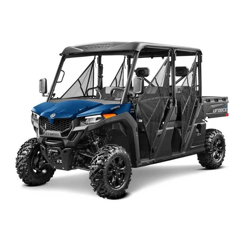
Cfmoto Uforce 800 XL (2025-2026) - Service Repair Manual - Wiring Diagrams
search
  • Cfmoto Uforce 800 XL (2025-2026) - Service Repair Manual - Wiring Diagrams

Cfmoto Uforce 800 XL (2025-2026) - Service Repair Manual - Wiring Diagrams

$29.95
$19.95 Save $10.00
No tax
Quantity

YOUTUBE Official Channel @SoloPDFcom (+18,000 subs). Trusted by mechanics worldwide using professional workshop manuals and wiring diagrams.

Cfmoto Uforce 800 XL (2025-2026) - Service Repair Manual - Wiring Diagrams

Digital technical documentation with sections on MODEL, Safety Information, Safety Instructions. Review the complete contents below for the systems and procedures covered.

Manual contents

  • 2025 MODEL
  • 01 Safety Information
  • - 1.1 Service Manual
  • - 1.2 Safety Instructions
  • - 1.3 Hazard Levels and Symbols
  • - 1.4 Operation Notice
  • - 1.5 General Precautions
  • - 1.5.1 Avoid Carbon Monoxide Poisoning
  • - 1.5.2 Avoid Corrosion Injury by Electrolyte
  • - 1.5.3 Avoid Injuries
  • - 1.5.4 Avoid Burns on High-temperature Parts
  • - 1.5.5 Avoid Toxic Liquid Coolants
  • - 1.5.6 Avoid Explosions or Fires
  • - 1.5.7 Operation Safety
  • - 1.6 Precautions for Disassembly and Assembly
  • - 1.7 Engine Break-in
  • - 1.8 Warranty
  • - 1.9 Fuel and Fluid Recommendations
  • - 1.10 Captions and Illustrations
  • 02 General Information
  • - 2.1 Unit Conversion Table and Symbols
  • - 2.2 Identification Number Locations
  • - 2.3 Main Specification Chart
  • - 2.4 Specifications for Service
  • - 2.5 Torque Table - Vehicle
  • - 2.6 Torque Table - Engine
  • - 2.7 Grease and Sealant
  • - 2.8 Engine Service Products
  • - 2.9 Engine Service Tools
  • 03 Maintenance Information
  • - 3.1 Maintenance Information
  • - 3.1.1 Pre-Ride Maintenance Checklist
  • - 3.1.2 Break-In Maintenance Checklist
  • - 3.1.3 Periodic Maintenance Schedule
  • 04 CVT and Transmission
  • - 4.1 CVT System
  • - 4.1.1 System Description
  • - 4.1.2 Special Tools
  • - 4.1.3 Drive Pulley Exploded View
  • - 4.1.4 Driven Pulley Exploded View
  • - 4.1.5 CVT Air Duct Exploded View
  • - 4.1.6 How-Avoid CVT Failure / Overheating and Diagnosis
  • - 4.1.7 CVT Draining and Drying Procedure (Water Ingress)
  • - 4.1.8 Drive Belt – Removal/Inspection/Replacement
  • - 4.2 CVT Removal/Overhaul/Installation
  • - 4.2.1 Removal
  • - 4.2.2 Drive Pulley Overhaul
  • - 4.2.2.1 Disassembly
  • - 4.2.2.2 Inspection
  • - 4.2.2.3 Reassembly
  • - 4.2.3 Driven Pulley Overhaul
  • - 4.2.3.1 Disassembly
  • - 4.2.3.2 Inspection
  • - 4.2.3.3 Reassembly
  • - 4.2.4 Installation
  • - 4.2.4.1 CVT Cover Installation
  • - 4.3 Transmission (Engine)
  • - 4.3.1 Special Tools
  • - 4.3.2 Transmission Exploded View
  • - 4.3.3 Transmission Overhaul
  • - 4.3.3.1 Gear Shift Assembly
  • - 4.3.3.2 Gearshift Cover
  • - 4.3.3.3 Gearshift Position Swing Arm, Drum Cam and Shift Drum
  • - 4.3.3.4 Shift Fork Assembly
  • - 4.3.3.5 Transmission Output Shaft
  • - 4.3.3.6 Transmission Driven Shaft Assembly
  • - 4.3.3.7 Drive Bevel Gear
  • - 4.3.3.8 Driven Bevel Gear
  • - 4.3.3.9 Output Shaft
  • - 4.3.3.10 Transmission Bevel Gear Backlash Adjustment
  • - 4.3.4 Gear Selector
  • - 4.3.4.1 Gear Selector Inspection
  • - 4.3.4.2 Shift Cable Adjustment
  • - 4.3.4.3 Gear Selector Removal
  • - 4.3.4.4 Shift Lever Inspection
  • - 4.3.4.5 Gear Selector Installation
  • 05 Engine
  • - 5.1 Special Tools
  • - 5.2 Engine Removal
  • - 5.3 Engine Disassembly
  • - 5.3.1 Engine and Transmission Oil Drain
  • - 5.3.2 CVT Case
  • - 5.3.3 Thermostat, Housing and Seat
  • - 5.3.4 Cylinder Head Covers
  • - 5.3.5 Spark Plug
  • - 5.3.6 Magneto Cover and Crankshaft Position Sensor
  • - 5.3.7 Setting Cylinder 2 TDC (Repair)
  • - 5.3.8 Cylinder 2 Tensioner
  • - 5.3.9 Cylinder 2 Head
  • - 5.3.10 Setting Cylinder 1 TDC (Repair)
  • - 5.3.11 Cylinder 1 Tensioner
  • - 5.3.12 Cylinder 1 Head
  • - 5.3.13 Oil Filter
  • - 5.3.14 Water Pump Cover
  • - 5.3.15 Starter Motor
  • - 5.3.16 Oil Cooler
  • - 5.3.17 PTO Crankcase Cover
  • - 5.3.18 Magneto Crankcase Cover
  • - 5.3.19 Starter Dual Gear
  • - 5.3.20 Magneto Rotor
  • - 5.3.21 Crankcase Breather
  • - 5.3.22 Oil pump
  • - 5.3.23 Cylinder 1 Timing Chain
  • - 5.3.24 Cylinder 2 Timing Chain
  • - 5.3.25 Gearshift Assembly
  • - 5.3.26 Cylinder and Piston 1
  • - 5.3.27 Cylinder and Piston 2
  • - 5.3.28 MAG and PTO Crankcase Disassembly
  • - 5.3.29 Crankshaft and Connecting Rod
  • - 5.3.30 Transmission Disassembly
  • - 5.4 Engine Parts Inspection
  • - 5.4.1 Cylinder Head Cover and Seal
  • - 5.4.2 Cylinder Head
  • - 5.4.2.1 Disassembly
  • - 5.4.2.2 Parts Inspection
  • - 5.4.2.3 Reassembly
  • - 5.4.3 Cylinder Body
  • - 5.4.4 Timing Chain Tensioner
  • - 5.4.5 Piston
  • - 5.4.6 Timing Sprocket
  • - 5.4.7 Timing Chain
  • - 5.4.8 Tension Plate, Chain Guide and Chain Guard
  • - 5.4.9 Water Pump Assembly
  • - 5.4.10 Oil Filter
  • - 5.4.11 Overriding Clutch
  • - 5.4.12 Magneto Rotor
  • - 5.4.13 Magneto Stator
  • - 5.4.14 Starter Gears
  • - 5.4.15 Oil Pump Gears
  • - 5.4.16 Oil Pump
  • - 5.4.17 Crankcase Breather Gears
  • - 5.4.18 Starter Driven Gear
  • - 5.4.19 Crankshaft Assembly
  • - 5.4.20 Thermostat and Coolant Temperature Sensor
  • - 5.4.21 PTO Crankcase
  • - 5.4.22 MAG Crankcase
  • - 5.4.23 Crankcase Plain Bearings
  • - 5.4.24 Magneto Crankcase Cover
  • - 5.4.25 CVT Case
  • - 5.4.26 PTO Crankcase Cover
  • - 5.4.27 Oil Cooler
  • - 5.4.28 Thermostat Seat and Water Pipe
  • - 5.5 Engine Assembly
  • - 5.5.1 Transmission Reassembly
  • - 5.5.2 Crankshaft Installation
  • - 5.5.3 Crankcase Reassembly
  • - 5.5.4 Gearshift Assembly Installation
  • - 5.5.5 Piston and Cylinder Installation
  • - 5.5.6 Timing Chain Installation
  • - 5.5.7 Cylinder Head Installation
  • - 5.5.8 Oil Pump Installation
  • - 5.5.9 Crankcase Breather Gear Installation
  • - 5.5.10 Magneto Rotor Installation
  • - 5.5.11 Starter Gear Installation
  • - 5.5.12 Magneto Crankcase Cover and Water Pump Cover Installation
  • - 5.5.13 Setting Cylinder 2 TDC (Overhaul)
  • - 5.5.14 Cylinder 2 Timing Sprocket Installation
  • - 5.5.15 Cylinder 2 Tensioner Installation
  • - 5.5.16 Cylinder 2 Valve Clearance Adjustment
  • - 5.5.17 Setting Cylinder 1 TDC (Overhaul)
  • - 5.5.18 Cylinder 1 Timing Sprocket Installation
  • - 5.5.19 Cylinder 1 Tensioner Installation
  • - 5.5.20 Cylinder 1 Valve Clearance Adjustment
  • - 5.5.21 Spark Plug Installation
  • - 5.5.22 Cylinder Head Cover Installation
  • - 5.5.23 Crankshaft Position Sensor and Strainer Cover Installation
  • - 5.5.24 Oil Cooler and Oil Filter Installation
  • - 5.5.25 Starter Motor Installation
  • - 5.5.26 Thermostat and Thermostat Seat Installation
  • - 5.5.27 PTO Crankcase Cover Installation
  • - 5.5.28 CVT Case Installation
  • - 5.5.29 Drain Bolt Installation
  • - 5.5.30 Oil Dipstick Installation
  • - 5.6 Engine Installation
  • - 5.7 Engine Coolant/Oil Heat Exchanger
  • - 5.8 Lubrication System
  • - 5.8.1 Engine Oil
  • - 5.8.1.1 Oil Level Inspection
  • - 5.8.1.2 Oil Replacement
  • - 5.8.2 Transmission Oil
  • - 5.8.2.1 Oil Level Inspection
  • - 5.8.2.2 Oil Replacement
  • - 5.8.3 Engine Oil Pressure Inspection
  • - 5.9 Air Intake System
  • - 5.9.1 Air Filter Maintenance
  • - 5.9.2 Air Filter Housing Assembly
  • - 5.9.3 Air Intake Manifold
  • - 5.10 Exhaust System
  • - 5.10.1 Removal
  • - 5.10.2 Inspection
  • - 5.10.3 Reassembly
  • 06 Vehicle Body and Body Covering Parts
  • - 6.1 Front Seat
  • - 6.1.1 Driver Seat Cushion
  • - 6.1.2 Passenger Seat Cushion
  • - 6.1.3 Passenger Seat Backrest
  • - 6.2 Rear Seat
  • - 6.2.1 Rear Seat Cushion
  • - 6.2.2 Rear Passenger Seat Backrest
  • - 6.2.3 Headrest Assembly
  • - 6.3 Front Panel and Headlight Assembly
  • - 6.3.1 Front Panel Latch
  • - 6.3.2 Headlight Guard
  • - 6.3.3 LH/RH Front Headlight
  • - 6.3.4 Front Headlight Panel
  • - 6.3.5 Front LH/RH Deco Plate
  • - 6.4 Front LH/RH Panels
  • - 6.5 Top Roof Assembly
  • - 6.5.1 Top Roof
  • - 6.5.2 Top Roof Bracket
  • - 6.6 Front LH/RH Upper Panels
  • - 6.7 Seat Protection Plate
  • - 6.8 Rear Seat Backplate
  • - 6.9 Rear LH Lower Panel
  • - 6.10 Rear RH Lower Panel
  • - 6.11 Rear LH/RH Upper Panels
  • - 6.12 Front LH/RH Lower Panels
  • - 6.13 Front Seat Backplate Assembly
  • - 6.13.1 Front Seat Backplate
  • - 6.13.2 USB/12 Volt Socket Cover
  • - 6.13.3 Rear Cup Holders and Accessory Sockets
  • - 6.14 Front Floorboard Service Cover
  • - 6.15 Rear Floorboard Service Cover
  • - 6.16 Seat Base Lower Panel
  • - 6.17 Rear Floorboard Section
  • - 6.18 Front Floorboard Section
  • - 6.19 Extended Floorboard
  • - 6.20 Front LH/RH Lower Inner Panel
  • - 6.21 Safety Belt Assembly
  • - 6.21.1 Safety Belt Buckle
  • - 6.21.2 Safety Belt Reel
  • - 6.22.3 Safety Belt Inspection
  • - 6.22 Cab Frame
  • - 6.22.1 Front Cab Assembly
  • - 6.22.2 Connecting Beams
  • - 6.22.4 Middle Cab Assembly
  • - 6.22.5 Rear Cab Assembly
  • - 6.22.6 Protection Pipe Assembly
  • - 6.23 Steering Wheel
  • - 6.24 Switch Panel Assembly
  • - 6.24.1 Switch Panel - With Turn Lights
  • - 6.24.2 Switch Panel - Without Turn Lights
  • - 6.25 Dashboard Upper Panel Assembly
  • - 6.25.1 Dashboard and Dashboard Deco Cover
  • - 6.25.1.1 Dashboard Replacement
  • - 6.25.2 Center Storage Box
  • - 6.25.3 Passenger Storage Box Cover
  • - 6.25.4 2WD/4WD Switch
  • - 6.25.5 Key Switch Assembly
  • - 6.25.6 Switch Assembly
  • - 6.25.7 Cup Holder
  • - 6.25.8 Dashboard Lower Panel Assembly
  • - 6.26 Coolant Reservoir Assembly
  • - 6.27 Brake Reservoir Assembly
  • - 6.28 Front Inner Lock Panel
  • - 6.29 Gearshift Assembly
  • - 6.29.1 Gearshift Mechanism Gearshift Head
  • - 6.30 Steering Mechanism Assembly
  • - 6.31 Throttle Pedal
  • - 6.32 Brake Pedal
  • - 6.33 Front Fender
  • - 6.34 Rear LH/RH Fender
  • - 6.35 Cargo Box
  • - 6.35.1 Gas Spring
  • - 6.35.2 Cargo Box
  • - 6.36 Skid Plate Assembly
  • - 6.36.1 Front Skid Plate
  • - 6.36.2 Rear Gear Case Skid Plate
  • - 6.36.3 Middle Skid Plate
  • - 6.36.4 Rear Middle Skid Plate
  • - 6.36.5 LH/RH Side Skid Plate
  • - 6.36.6 LH/RH Rear Side Skid Plate
  • 07 Powertrain System
  • - 7.1 Maintenance and Troubleshooting
  • - 7.1.1 Maintenance Information
  • - 7.1.2 Troubleshooting
  • - 7.2 CV Shaft
  • - 7.2.1 Removal
  • - 7.2.2 CV Shaft Inspection and Maintenance
  • - 7.2.3 CV Shaft Dust Boot and Universal Joint
  • - 7.3 Drive Shafts
  • - 7.3.1 Front Drive Shaft Removal
  • - 7.3.2 Rear Drive Shaft Removal
  • - 7.3.2.1 Drive Shafts Inspection
  • - 7.3.3 Universal Joint Installation
  • - 7.3.4 Drive Shaft Assembly
  • - 7.3.4.1 Front Drive Shaft Installation
  • - 7.3.4.2 Rear Drive Shaft Installation
  • - 7.4 Front Gear Case
  • - 7.4.1 Removal
  • - 7.4.2 Disassembly
  • - 7.4.3 Front Drive Bevel Gear Disassembly
  • - 7.4.4 Differential Disassembly
  • - 7.4.4.1 Reassembly
  • - 7.4.5 Component Inspection
  • - 7.4.6 Front Drive Bevel Gear Reassembly
  • - 7.5 Rear Gear Case and Drive Shaft
  • - 7.5.1 Removal/Installation
  • - 7.6 Rear Gear Case (Non-Differential)
  • - 7.6.1 Disassembly
  • - 7.6.2 Driven Bevel Gear Disassembly
  • - 7.6.2.1 Reassembly
  • - 7.6.3 Drive Bevel Gear Disassembly
  • - 7.6.3.1 Reassembly
  • - 7.7 Rear Gear Case (Differential with Diff-Lock)
  • - 7.7.1 Disassembly
  • - 7.7.1.1 Differential Disassembly
  • - 7.7.2 Component Inspection
  • - 7.7.3 Reassembly
  • - 7.7.3.1 Differential Reassembly
  • - 7.7.3.2 Drive Bevel Gear Reassembly
  • - 7.7.4 Adjust Rear Gear Case Backlash
  • 08 Brake System
  • - 8.1 Brake System View
  • - 8.2 Brake Noise Troubleshooting
  • - 8.3 Hand Brake Assembly
  • - 8.4 Brake System
  • - 8.4.1 Brake Calipers
  • - 8.4.2 Brake Disc and Mounting Bracket
  • - 8.4.3 Master Cylinder
  • - 8.5 Brake Fluid
  • - 8.6 Brake Fluid Replacement
  • - 8.7 Brake Pedal
  • - 8.8 Parking System
  • 09 Suspension System
  • - 9.1 Tire
  • - 9.1.1 Wheel Toe-in
  • - 9.2 Wheel Hubs
  • - 9.3 Suspension
  • - 9.3.1 Front Shock Absorber
  • - 9.3.2 Rear Shock Absorber
  • - 9.3.3 Steering Knuckle
  • - 9.3.4 Front Swing Arm
  • - 9.3.5 Rear Bearing Carrier
  • - 9.3.6 Rear Swing Arm
  • - 9.3.7 Rear Sway Bar
  • 10 Steering System
  • - 10.1 Steering Wheel
  • - 10.1.1 Steering Column and Steering Wheel Inspection
  • - 10.1.2 Steering Wheel Height Adjustment
  • - 10.1.3 Upper Steering Shaft Assembly
  • - 10.1.4 Adjust the Initial Position of Steering Wheel
  • - 10.1.5 Removal and Installation of Steering Wheel
  • - 10.1.6 Gas Spring Assembly
  • - 10.1.7 Upper Steering Universal Shaft Assemy
  • - 10.2 EPS Drive Removal and Installation
  • - 10.3 Steering Motor
  • - 10.4 Removal and Installation of Steering Rod
  • - 10.5 Gearshift Assembly
  • - 10.6 Shift Lever Position Inspection
  • - 10.7 Gearshift Cable Adjustment
  • 11 Cooling System
  • - 11.1 Coolant Specification
  • - 11.2 Cooling System View
  • - 11.3 Cooling System
  • - 11.4 Cooling System Pipes
  • - 11.5 Fan Motor
  • - 11.6 Fan Troubleshooting
  • - 11.7 Water Pump Maintenance
  • - 11.8 Cooling System Sealing Inspection
  • - 11.9 Coolant Replacement and Venting
  • - 11.9.1 Coolant Replacement
  • - 11.9.2 Air Bleeding
  • 12 Electrical System
  • - 12.1 Service Tool
  • - 12.2 Lights
  • - 12.2.1 Lights View
  • - 12.2.2 Headlight Inspection
  • - 12.2.3 Tail Light Inspection
  • - 12.2.4 Brake Light Inspection
  • - 12.2.5 Turn Light Inspection (If equipped)
  • - 12.3 Fuse and Relay Box
  • - 12.3.1 Fuse and Relay Box Guide
  • - 12.3.2 Fuse and Relay Box
  • - 12.4 Switch Inspections and Testing
  • - 12.4.1 Switch Function Diagrams
  • - 12.5 Charging System and Battery
  • - 12.5.1 Charging Wire Diagram
  • - 12.5.2 Battery
  • - 12.5.3 Battery Leakage Test
  • - 12.5.4 Regulator
  • - 12.5.5 Magneto Stator
  • - 12.5.5.1 Magneto Coil Inspection
  • - 12.6 Electric Horn
  • - 12.7 Starting System
  • - 12.7.1 Starter Relay
  • - 12.7.1.1 Starter Relay Path Inspection
  • - 12.7.1.2 Starter Relay Operation Inspection
  • - 12.7.2 Starter Motor
  • - 12.7.2.1 Appearance Inspection of Starter Motor
  • - 12.7.2.2 Starter Motor Work Inspection
  • - 12.7.3 Trigger
  • - 12.7.3.1 Trigger Peak Voltage Inspection
  • - 12.7.3.2 Trigger Resistance Inspection
  • - 12.8 EVAP/Fuel Pump
  • - 12.8.1 EVAP System Guide
  • - 12.8.2 Carbon Tank Test
  • - 12.8.3 Canister Magnetic Valve Test
  • - 12.8.4 Fuel Pump
  • - 12.8.4.1 Fuel Pump Pressure Test
  • - 12.8.4.2 Fuel Pump Removal
  • - 12.8.4.3 Fuel Level Sensor Detection
  • - 12.9 EFI System
  • - 12.9.1 EFI Structure
  • - 12.9.2 Sensors
  • - 12.9.3 ECM
  • - 12.9.4 Actuators
  • - 12.9.5 EFI System Maintenance Notice
  • - 12.9.6 Throttle Body Assembly
  • - 12.9.7 Ignition Coil
  • - 12.9.8 Water Temperature Sensor
  • - 12.9.9 Oxygen Sensor
  • - 12.9.10 Injector
  • - 12.9.10.1 Injector Resistance Detection
  • - 12.9.10.2 Injector Input Voltage Detection
  • - 12.9.11 Air Intake Pressure Temperature Sensor
  • - 12.9.12 ECU
  • - 12.10 T-BOX
  • - 12.10.1 T-BOX Pin
  • - 12.10.2 T-BOX Troubleshooting:
  • - 12.11 Fault Code Table
  • - 12.11.1 ECU Fault Code Table
  • - 12.11.2 Trouble Diagnosis In Accordance With Engine Error
  • Wire Diagram
  • 2026 MODEL
  • 01 Safety Information
  • - 1.1 Service Manual
  • - 1.2 Safety Instructions
  • - 1.3 Hazard Levels and Symbols
  • - 1.4 Operation Notice
  • - 1.5 General Precautions
  • - 1.5.1 Avoid Carbon Monoxide Poisoning
  • - 1.5.2 Avoid Corrosion Injury by Electrolyte
  • - 1.5.3 Avoid Injuries
  • - 1.5.4 Avoid Burns on High-temperature Parts
  • - 1.5.5 Avoid Toxic Liquid Coolants
  • - 1.5.6 Avoid Explosions or Fires
  • - 1.5.7 Operation Safety
  • - 1.6 Precautions for Disassembly and Assembly
  • - 1.7 Engine Break-in
  • - 1.8 Warranty
  • - 1.9 Fuel and Fluid Recommendations
  • - 1.10 Captions and Illustrations
  • 02 General Information
  • - 2.1 Unit Conversion Table and Symbols
  • - 2.2 Identification Number Locations
  • - 2.3 Main Specification Chart
  • - 2.4 Specifications for Service
  • - 2.5 Torque Table - Vehicle
  • - 2.6 Torque Table - Engine
  • - 2.7 Grease and Sealant
  • - 2.8 Engine Service Products
  • - 2.9 Engine Service Tools
  • 03 Maintenance Information
  • - 3.1 Maintenance Information
  • - 3.1.1 Pre-Ride Maintenance Checklist
  • - 3.1.2 Break-In Maintenance Checklist
  • - 3.1.3 Periodic Maintenance Schedule
  • 04 CVT and Transmission
  • - 4.1 CVT System
  • - 4.1.1 System Description
  • - 4.1.2 Special Tools
  • - 4.1.3 Drive Pulley Exploded View
  • - 4.1.4 Driven Pulley Exploded View
  • - 4.1.5 CVT Air Duct Exploded View
  • - 4.1.6 How-Avoid CVT Failure / Overheating and Diagnosis
  • - 4.1.7 CVT Draining and Drying Procedure (Water Ingress)
  • - 4.1.8 Drive Belt – Removal/Inspection/Replacement
  • - 4.2 CVT Removal/Overhaul/Installation
  • - 4.2.1 Removal
  • - 4.2.2 Drive Pulley Overhaul
  • - 4.2.2.1 Disassembly
  • - 4.2.2.2 Inspection
  • - 4.2.2.3 Reassembly
  • - 4.2.3 Driven Pulley Overhaul
  • - 4.2.3.1 Disassembly
  • - 4.2.3.2 Inspection
  • - 4.2.3.3 Reassembly
  • - 4.2.4 Installation
  • - 4.2.4.1 CVT Cover Installation
  • - 4.3 Transmission (Engine)
  • - 4.3.1 Special Tools
  • - 4.3.2 Transmission Exploded View
  • - 4.3.3 Transmission Overhaul
  • - 4.3.3.1 Gear Shift Assembly
  • - 4.3.3.2 Gearshift Cover
  • - 4.3.3.3 Gearshift Position Swing Arm, Drum Cam and Shift Drum
  • - 4.3.3.4 Shift Fork Assembly
  • - 4.3.3.5 Transmission Output Shaft
  • - 4.3.3.6 Transmission Driven Shaft Assembly
  • - 4.3.3.7 Drive Bevel Gear
  • - 4.3.3.8 Driven Bevel Gear
  • - 4.3.3.9 Output Shaft
  • - 4.3.3.10 Transmission Bevel Gear Backlash Adjustment
  • - 4.3.4 Gear Selector
  • - 4.3.4.1 Gear Selector Inspection
  • - 4.3.4.2 Shift Cable Adjustment
  • - 4.3.4.3 Gear Selector Removal
  • - 4.3.4.4 Shift Lever Inspection
  • - 4.3.4.5 Gear Selector Installation
  • 05 Engine
  • - 5.1 Special Tools
  • - 5.2 Engine Removal
  • - 5.3 Engine Disassembly
  • - 5.3.1 Engine and Transmission Oil Drain
  • - 5.3.2 CVT Case
  • - 5.3.3 Thermostat, Housing and Seat
  • - 5.3.4 Cylinder Head Covers
  • - 5.3.5 Spark Plug
  • - 5.3.6 Magneto Cover and Crankshaft Position Sensor
  • - 5.3.7 Setting Cylinder 2 TDC (Repair)
  • - 5.3.8 Cylinder 2 Tensioner
  • - 5.3.9 Cylinder 2 Head
  • - 5.3.10 Setting Cylinder 1 TDC (Repair)
  • - 5.3.11 Cylinder 1 Tensioner
  • - 5.3.12 Cylinder 1 Head
  • - 5.3.13 Oil Filter
  • - 5.3.14 Water Pump Cover
  • - 5.3.15 Starter Motor
  • - 5.3.16 Oil Cooler
  • - 5.3.17 PTO Crankcase Cover
  • - 5.3.18 Magneto Crankcase Cover
  • - 5.3.19 Starter Dual Gear
  • - 5.3.20 Magneto Rotor
  • - 5.3.21 Crankcase Breather
  • - 5.3.22 Oil pump
  • - 5.3.23 Cylinder 1 Timing Chain
  • - 5.3.24 Cylinder 2 Timing Chain
  • - 5.3.25 Gearshift Assembly
  • - 5.3.26 Cylinder and Piston 1
  • - 5.3.27 Cylinder and Piston 2
  • - 5.3.28 MAG and PTO Crankcase Disassembly
  • - 5.3.29 Crankshaft and Connecting Rod
  • - 5.3.30 Transmission Disassembly
  • - 5.4 Engine Parts Inspection
  • - 5.4.1 Cylinder Head Cover and Seal
  • - 5.4.2 Cylinder Head
  • - 5.4.2.1 Disassembly
  • - 5.4.2.2 Parts Inspection
  • - 5.4.2.3 Reassembly
  • - 5.4.3 Cylinder Body
  • - 5.4.4 Timing Chain Tensioner
  • - 5.4.5 Piston
  • - 5.4.6 Timing Sprocket
  • - 5.4.7 Timing Chain
  • - 5.4.8 Tension Plate, Chain Guide and Chain Guard
  • - 5.4.9 Water Pump Assembly
  • - 5.4.10 Oil Filter
  • - 5.4.11 Overriding Clutch
  • - 5.4.12 Magneto Rotor
  • - 5.4.13 Magneto Stator
  • - 5.4.14 Starter Gears
  • - 5.4.15 Oil Pump Gears
  • - 5.4.16 Oil Pump
  • - 5.4.17 Crankcase Breather Gears
  • - 5.4.18 Starter Driven Gear
  • - 5.4.19 Crankshaft Assembly
  • - 5.4.20 Thermostat and Coolant Temperature Sensor
  • - 5.4.21 PTO Crankcase
  • - 5.4.22 MAG Crankcase
  • - 5.4.23 Crankcase Plain Bearings
  • - 5.4.24 Magneto Crankcase Cover
  • - 5.4.25 CVT Case
  • - 5.4.26 PTO Crankcase Cover
  • - 5.4.27 Oil Cooler
  • - 5.4.28 Thermostat Seat and Water Pipe
  • - 5.5 Engine Assembly
  • - 5.5.1 Transmission Reassembly
  • - 5.5.2 Crankshaft Installation
  • - 5.5.3 Crankcase Reassembly
  • - 5.5.4 Gearshift Assembly Installation
  • - 5.5.5 Piston and Cylinder Installation
  • - 5.5.6 Timing Chain Installation
  • - 5.5.7 Cylinder Head Installation
  • - 5.5.8 Oil Pump Installation
  • - 5.5.9 Crankcase Breather Gear Installation
  • - 5.5.10 Magneto Rotor Installation
  • - 5.5.11 Starter Gear Installation
  • - 5.5.12 Magneto Crankcase Cover and Water Pump Cover Installation
  • - 5.5.13 Setting Cylinder 2 TDC (Overhaul)
  • - 5.5.14 Cylinder 2 Timing Sprocket Installation
  • - 5.5.15 Cylinder 2 Tensioner Installation
  • - 5.5.16 Cylinder 2 Valve Clearance Adjustment
  • - 5.5.17 Setting Cylinder 1 TDC (Overhaul)
  • - 5.5.18 Cylinder 1 Timing Sprocket Installation
  • - 5.5.19 Cylinder 1 Tensioner Installation
  • - 5.5.20 Cylinder 1 Valve Clearance Adjustment
  • - 5.5.21 Spark Plug Installation
  • - 5.5.22 Cylinder Head Cover Installation
  • - 5.5.23 Crankshaft Position Sensor and Strainer Cover Installation
  • - 5.5.24 Oil Cooler and Oil Filter Installation
  • - 5.5.25 Starter Motor Installation
  • - 5.5.26 Thermostat and Thermostat Seat Installation
  • - 5.5.27 PTO Crankcase Cover Installation
  • - 5.5.28 CVT Case Installation
  • - 5.5.29 Drain Bolt Installation
  • - 5.5.30 Oil Dipstick Installation
  • - 5.6 Engine Installation
  • - 5.7 Engine Coolant/Oil Heat Exchanger
  • - 5.8 Lubrication System
  • - 5.8.1 Engine Oil
  • - 5.8.1.1 Oil Level Inspection
  • - 5.8.1.2 Oil Replacement
  • - 5.8.2 Transmission Oil
  • - 5.8.2.1 Oil Level Inspection
  • - 5.8.2.2 Oil Replacement
  • - 5.8.3 Engine Oil Pressure Inspection
  • - 5.9 Air Intake System
  • - 5.9.1 Air Filter Maintenance
  • - 5.9.2 Air Filter Housing Assembly
  • - 5.9.3 Air Intake Manifold
  • - 5.10 Exhaust System
  • - 5.10.1 Removal
  • - 5.10.2 Inspection
  • - 5.10.3 Reassembly
  • 06 Vehicle Body and Body Covering Parts
  • - 6.1 Front Seat
  • - 6.1.1 Driver Seat Cushion
  • - 6.1.2 Passenger Seat Cushion
  • - 6.1.3 Passenger Seat Backrest
  • - 6.2 Rear Seat
  • - 6.2.1 Rear Seat Cushion
  • - 6.2.2 Rear Passenger Seat Backrest
  • - 6.2.3 Headrest Assembly
  • - 6.3 Front Panel and Headlight Assembly
  • - 6.3.1 Front Panel Latch
  • - 6.3.2 Headlight Guard
  • - 6.3.3 LH/RH Front Headlight
  • - 6.3.4 Front Headlight Panel
  • - 6.3.5 Front LH/RH Deco Plate
  • - 6.4 Front LH/RH Panels
  • - 6.5 Top Roof Assembly
  • - 6.5.1 Top Roof
  • - 6.5.2 Top Roof Bracket
  • - 6.6 Front LH/RH Upper Panels
  • - 6.7 Seat Protection Plate
  • - 6.8 Rear Seat Backplate
  • - 6.9 Rear LH Lower Panel
  • - 6.10 Rear RH Lower Panel
  • - 6.11 Rear LH/RH Upper Panels
  • - 6.12 Front LH/RH Lower Panels
  • - 6.13 Front Seat Backplate Assembly
  • - 6.13.1 Front Seat Backplate
  • - 6.13.2 USB/12 Volt Socket Cover
  • - 6.13.3 Rear Cup Holders and Accessory Sockets
  • - 6.14 Front Floorboard Service Cover
  • - 6.15 Rear Floorboard Service Cover
  • - 6.16 Seat Base Lower Panel
  • - 6.17 Rear Floorboard Section
  • - 6.18 Front Floorboard Section
  • - 6.19 Extended Floorboard
  • - 6.20 Front LH/RH Lower Inner Panel
  • - 6.21 Safety Belt Assembly
  • - 6.21.1 Safety Belt Buckle
  • - 6.21.2 Safety Belt Reel
  • - 6.22.3 Safety Belt Inspection
  • - 6.22 Cab Frame
  • - 6.22.1 Front Cab Assembly
  • - 6.22.2 Connecting Beams
  • - 6.22.4 Middle Cab Assembly
  • - 6.22.5 Rear Cab Assembly
  • - 6.22.6 Protection Pipe Assembly
  • - 6.23 Steering Wheel
  • - 6.24 Switch Panel Assembly
  • - 6.24.1 Switch Panel - With Turn Lights
  • - 6.24.2 Switch Panel - Without Turn Lights
  • - 6.25 Dashboard Upper Panel Assembly
  • - 6.25.1 Dashboard and Dashboard Deco Cover
  • - 6.25.1.1 Dashboard Replacement
  • - 6.25.2 Center Storage Box
  • - 6.25.3 Passenger Storage Box Cover
  • - 6.25.4 2WD/4WD Switch
  • - 6.25.5 Key Switch Assembly
  • - 6.25.6 Switch Assembly
  • - 6.25.7 Cup Holder
  • - 6.25.8 Dashboard Lower Panel Assembly
  • - 6.26 Coolant Reservoir Assembly
  • - 6.27 Brake Reservoir Assembly
  • - 6.28 Front Inner Lock Panel
  • - 6.29 Gearshift Assembly
  • - 6.29.1 Gearshift Mechanism Gearshift Head
  • - 6.30 Steering Mechanism Assembly
  • - 6.31 Throttle Pedal
  • - 6.32 Brake Pedal
  • - 6.33 Front Fender
  • - 6.34 Rear LH/RH Fender
  • - 6.35 Cargo Box
  • - 6.35.1 Gas Spring
  • - 6.35.2 Cargo Box
  • - 6.36 Skid Plate Assembly
  • - 6.36.1 Front Skid Plate
  • - 6.36.2 Rear Gear Case Skid Plate
  • - 6.36.3 Middle Skid Plate
  • - 6.36.4 Rear Middle Skid Plate
  • - 6.36.5 LH/RH Side Skid Plate
  • - 6.36.6 LH/RH Rear Side Skid Plate
  • 07 Powertrain System
  • - 7.1 Maintenance and Troubleshooting
  • - 7.1.1 Maintenance Information
  • - 7.1.2 Troubleshooting
  • - 7.2 CV Shaft
  • - 7.2.1 Removal
  • - 7.2.2 CV Shaft Inspection and Maintenance
  • - 7.2.3 CV Shaft Dust Boot and Universal Joint
  • - 7.3 Drive Shafts
  • - 7.3.1 Front Drive Shaft Removal
  • - 7.3.2 Rear Drive Shaft Removal
  • - 7.3.2.1 Drive Shafts Inspection
  • - 7.3.3 Universal Joint Installation
  • - 7.3.4 Drive Shaft Assembly
  • - 7.3.4.1 Front Drive Shaft Installation
  • - 7.3.4.2 Rear Drive Shaft Installation
  • - 7.4 Front Gear Case
  • - 7.4.1 Removal
  • AND MORE...