• -$10.00
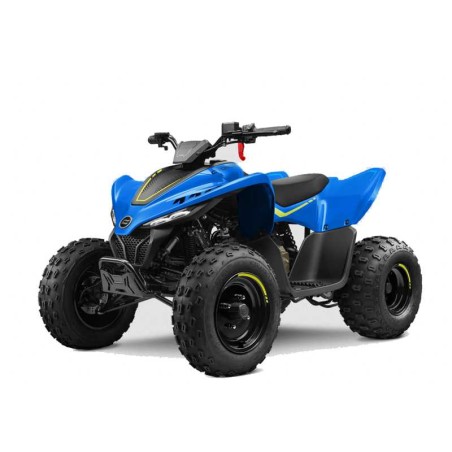
Cfmoto Cforce 110 from 2022 - Service & Wiring Diagram Manual
search
  • Cfmoto Cforce 110 from 2022 - Service & Wiring Diagram Manual

Cfmoto Cforce 110 from 2022 - Service & Wiring Diagram Manual

$29.95
$19.95 Save $10.00
No tax
Quantity

YOUTUBE Official Channel @SoloPDFcom (+18,000 subs). Trusted by mechanics worldwide using professional workshop manuals and wiring diagrams.

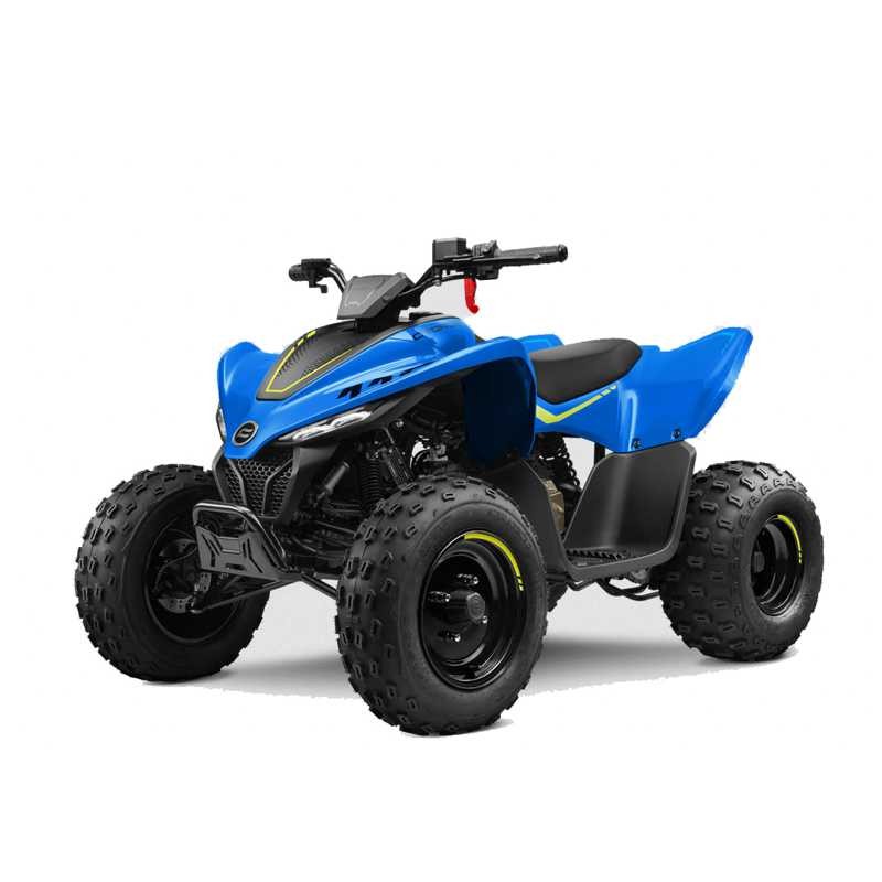
Cfmoto Cforce 110 from 2022 — Service & Wiring Diagram Manual

This download contains vehicle service procedures and the electrical wiring diagram in the appendix for Cfmoto Cforce 110 from 2022. The original technical index is retained below; indexed system names do not imply unlisted procedures.

Original document details

  • Full Service Manual & Repair Guide and Wiring Diagrams for vehicles Cfmoto Cforce 110 from 2022.

Selected indexed topics: APPENDIX (ELECTRICAL WIRING DIAGRAM); 9.9.1 Charging System Wiring; 9.10 EFI System.

Original technical index

  • 01 SAFETY INFORMATION
  • - 1.1 Service Manual
  • - 1.2 Safety Instruction
  • - 1.3 Hazard Level and Symbols
  • - 1.4 Operation Regulation
  • - 1.5 General Precautions
  • - 1.5.1 Avoid Carbon Monoxide Poisoning
  • - 1.5.2 Avoid Battery Solution Corrosion
  • - 1.5.3 Avoid Injuries
  • - 1.5.4 Avoid Burns on High-temperature Parts
  • - 1.5.5 Avoid Toxic Liquid Coolants
  • - 1.5.6 Avoid Explosions or Fires
  • - 1.5.7 Operation Safety
  • - 1.6 Precautions for Disassembly and Assembly
  • - 1.7 Engine Break-in
  • - 1.8 Warranty
  • - 1.9 Fuel, Auxiliary Materials
  • - 1.10 Illustrations
  • 02 TECHNICAL INFORMATION
  • - 2.1 Unit Conversion Table and Symbol Used in the Manual
  • - 2.2 VIN and EIN Location
  • - 2.3 Main Parameters
  • - 2.4 Maintenance Parameter
  • - 2.5 Tighten Torque
  • - 2.6 Grease Lubricant, Sealant
  • - 2.7 Engine Maintenance Materials
  • - 2.8 Engine Maintenance Tools
  • 03 MAINTENANCE INFORMATION
  • - 3.1 Maintenance Information
  • - 3.1.1 Pre-ride Maintenance Checklist
  • - 3.1.2 Break-in Maintenance Schedule
  • - 3.1.3 Periodic Maintenance Schedule
  • 04 VEHICLE PARTS
  • - 4.1 Seat
  • - 4.2 Foot Pedal
  • - 4.2.1 RH Foot Pedal
  • - 4.2.2 LH Foot Pedal
  • - 4.3 Fuel Tank Cover
  • - 4.3.1 Fuel Tank Rear Cover
  • - 4.3.2 Fuel Tank Front Cover
  • - 4.4 Side Cover Deco Plate
  • - 4.4.1 RH Side Cover Deco Plate
  • - 4.4.2 LH Side Cover Deco Plate
  • - 4.5 Fender
  • - 4.5.1 Rear Fender
  • - 4.5.2 Front Fender
  • - 4.6 Rim Deco Cover
  • - 4.7 Dashboard Guard
  • - 4.8 Inspection
  • - 4.8.1 RH Side Cover Deco Plate
  • - 4.8.2 LH Side Cover Deco Plate
  • - 4.8.3 Rear Fender
  • - 4.8.4 Tail Light
  • - 4.8.5 Front Fender
  • - 4.8.6 Dashboard Cover
  • - 4.9 Installation
  • 05 ENGINE
  • - 5.1 Special Tools
  • - 5.2 Overview
  • - 5.2.1 Specification
  • - 5.2.1.1 Engine Specification
  • - 5.2.1.2 Lubrication Specification
  • - 5.2.1.3 Cylinder Head/Valve Specification
  • - 5.2.1.4 Clutch and Gearshift Specification
  • - 5.2.1.5 Crankcase and Drivetrain Specification
  • - 5.2.1.6 Magneto and Starter Clutch Specification
  • - 5.2.1.7 Crankshaft, Piston and Cylinder Specification
  • - 5.2.2 Torque Value
  • - 5.2.2.1 Standard Parts
  • - 5.2.2.2 Engine
  • - 5.2.2.3 Cylinder Head and Valve
  • - 5.2.2.4 Clutch and Gearshift
  • - 5.2.2.5 Magneto and Starter Clutch
  • - 5.2.2.6 Crankcase
  • - 5.2.2.7 Crankshaft, Piston and Cylinder
  • - 5.2.3 Lubrication and Seal Position
  • - 5.3 Maintenance
  • - 5.3.1 Spark Plug
  • - 5.3.1.1 Spark Plug Removal
  • - 5.3.1.2 Spark Plug Inspection
  • - 5.3.2 Valve Clearance
  • - 5.3.2.1 Inspection
  • - 5.3.2.2 Adjustment
  • - 5.3.3 Engine Oil
  • - 5.3.3.1 Oil Level Inspection
  • - 5.3.3.2 Engine Oil Changing
  • - 5.3.4 Engine Oil Strainer
  • - 5.3.5 Engine Centrifugal Filter (status 1)
  • - 5.3.6 Engine Centrifugal Filter (status 2)
  • - 5.3.7 Engine Idle Speed
  • - 5.4 Engine Intake/Exhaust System
  • - 5.4.1 Air Filter
  • - 5.4.1.1 Air Filter Assembly
  • - 5.4.2 Engine Intake Pipe
  • - 5.4.3 Exhaust System
  • - 5.4.3.1 Muffler Assembly Removal
  • - 5.5 Oil Cooling System
  • - 5.6 Engine Removal from Vehicle
  • - 5.7 Lubrication System
  • - 5.7.1 Service Information
  • - 5.7.1.1 Overview
  • - 5.7.2 Lubrication System Specification
  • - 5.7.3 Trouble Shooting
  • - 5.7.4 Oil Pump
  • - 5.7.4.1 Removal/Installation
  • - 5.7.4.2 Disassembly/Assembly
  • - 5.7.4.3 Inspection
  • - 5.8 Cylinder Head and Valve
  • - 5.8.1 Service Information
  • - 5.8.1.1 Overview
  • - 5.8.2 Cylinder Head/Valve Specification
  • - 5.8.3 Trouble Shooting
  • - 5.8.4 Component Location
  • - 5.8.5 Cylinder Compression Test
  • - 5.8.6 Camshaft/Swing arm
  • - 5.8.6.1 Removal
  • - 5.8.6.2 Inspection
  • - 5.8.6.3 Installation
  • - 5.8.7 Cylinder Head/Valve
  • - 5.8.7.1 Removal
  • - 5.8.7.2 Disassembly
  • - 5.8.7.3 Inspection
  • - 5.8.7.4 Valve/Valve Guide
  • - 5.8.7.5 Valve Installation
  • - 5.8.8 Timing Chain/Sprocket
  • - 5.8.8.1 Chain Tensioner
  • - 5.9 Piston/Cylinder
  • - 5.9.1 Service Information
  • - 5.9.2 Specifications
  • - 5.9.3 Trouble Shooting
  • - 5.9.4 Cylinder Body/Piston Removal
  • - 5.9.4.1 Cylinder Removal
  • - 5.9.4.2 Piston Removal
  • - 5.9.5 Inspection
  • - 5.9.5.1 Cylinder
  • - 5.9.5.2 Piston/Piston Ring
  • - 5.9.5.3 Connecting Rod
  • - 5.9.6 Cylinder Stud Replacement
  • - 5.9.6.1 Piston Installation
  • - 5.10 Clutch and Gearshift (status 1)
  • - 5.10.1 Service Information
  • - 5.10.2 Clutch and Gearshift Specification
  • - 5.10.3 Trouble Shooting
  • - 5.10.4 Component Placement
  • - 5.11 Clutch and Gearshift (status 2)
  • - 5.11.1 Service Information
  • - 5.11.2 Clutch and Gearshift Specification
  • - 5.11.3 Trouble Shooting
  • - 5.11.4 Component Placement
  • - 5.11.5 RH Crankcase Cover (status 1)
  • - 5.11.5.1 Removal
  • - 5.11.5.2 Installation
  • - 5.11.6 RH Crankcase Cover (status 2)
  • - 5.11.6.1 Removal
  • - 5.11.6.2 Installation
  • - 5.11.7 Clutch (status 1)
  • - 5.11.7.1 Removal
  • - 5.11.7.2 Installation
  • - 5.11.7.3 Inspection
  • - 5.11.8 Clutch (status 2)
  • - 5.11.8.1 Removal
  • - 5.11.8.2 Disassembly
  • - 5.11.8.3 Inspection
  • - 5.11.9 Gearshift (status 1)
  • - 5.11.9.1 Removal
  • - 5.11.9.2 Inspection
  • - 5.11.9.3 Installation
  • - 5.11.10 Gearshift (status 2)
  • - 5.11.10.1 Removal
  • - 5.11.10.2 Inspection
  • - 5.11.10.3 Installation
  • - 5.12 Magneto and Starter Clutch
  • - 5.12.1 Service Information
  • - 5.12.2 Magneto and Starter Clutch Specification
  • - 5.12.3 Trouble Shooting
  • - 5.12.4 Component Location Relationship
  • - 5.12.5 LH Front Cover
  • - 5.12.5.1 Removal/Installation
  • - 5.12.6 Magneto Stator and Trigger
  • - 5.12.6.1 Removal/Installation
  • - 5.12.7 Magneto Rotor
  • - 5.12.7.1 Removal
  • - 5.12.7.2 Installation
  • - 5.12.8 Starter Clutch
  • - 5.12.8.1 Inspection
  • - 5.12.8.2 Removal/Installation
  • - 5.13 Crankcase and Drivetrain
  • - 5.13.1 Service Information
  • - 5.13.2 Crankcase and Drivetrain Specification
  • - 5.13.3 Trouble Shooting
  • - 5.13.4 Component Placement
  • - 5.13.5 Crankcase
  • - 5.13.5.1 Removal/Installation
  • - 5.13.5.2 Inspection
  • - 5.13.6 Drivetrain
  • - 5.13.6.1 Removal
  • - 5.13.6.2 Disassembly
  • - 5.13.6.3 Inspection
  • - 5.14 Trouble Shooting
  • - 5.14.1 Engine Does Not Start or Has Difficulty Starting
  • - 5.14.2 Engine Performs Poorly at Low or Idle Speeds
  • - 5.14.3 Engine Performs Poorly at High Speeds
  • - 5.14.4 Strange Noise from Engine
  • - 5.15 Engine Installation
  • 06 BRAKE SYSTEM
  • - 6.1 Brake System
  • - 6.1.1 Brake Caliper
  • - 6.1.2 Brake Pump
  • - 6.1.3 Hydraulic Distribution Valve
  • - 6.1.4 Brake Pedal
  • - 6.1.5 Brake Handle
  • - 6.2 Inspection
  • - 6.2.1 brake pad
  • - 6.2.2 brake disc
  • - 6.3 Brake Fluid
  • - 6.3.1 Brake Fluid Addition
  • - 6.3.2 Inspection
  • - 6.3.3 Brake Fluid Changing and Brake Exhausting
  • - 6.3.4 Rear Brake Fluid Changing and Brake Exhausting
  • - 6.4 Installation
  • 07 SUSPENSION
  • - 7.1 Tire
  • - 7.1.1 Wheel Toe-in
  • - 7.2 Shock Absorber
  • - 7.2.1 Front Shock Absorber
  • - 7.2.2 Rear Shock Absorber
  • - 7.3 Front Suspension
  • - 7.4 Rear Suspension
  • - 7.4.1 Chain
  • - 7.4.2 Rear Swing Arm
  • - 7.5 Rear Suspension Assembly
  • - 7.5.1 Rear Swing arm
  • - 7.5.2 Rear Bumper
  • 08 STEERING SYSTEM
  • - 8.1 Handlebar
  • - 8.2 Steering System
  • - 8.2.1 Steering Assembly
  • - 8.2.2 Inspection
  • - 8.3 Installation
  • 09 ELECTRICAL SYSTEM
  • - 9.1 Diagnosis Tools
  • - 9.2 Signal and Illumination System
  • - 9.2.1 Battery
  • - 9.2.2 Charging Voltage Inspection
  • - 9.3 Ground Wire Inspection
  • - 9.4 Fuse Box
  • - 9.5 Light Maintenance Information
  • - 9.6 Light Removal and Installation
  • - 9.7 Horn
  • - 9.8 Switches
  • - 9.9 Charging System
  • - 9.9.1 Charging System Wiring
  • - 9.9.2 Starter Relay
  • - 9.9.3 Main Relay and Fuel Pump Relay
  • - 9.9.4 Engine Starting Note
  • - 9.10 EFI System
  • - 9.10.1 EFI Structure
  • - 9.10.2 Sensors
  • - 9.10.3 ECU
  • - 9.10.4 Actuators
  • - 9.10.5 EFI System Maintenance Note
  • - 9.11 Structure and Performance of EFI Parts
  • - 9.11.1 ECU
  • - 9.11.2 Throttle Body Assembly
  • - 9.11.3 Cylinder Temperature Sensor
  • - 9.11.4 Oxygen Sensor
  • - 9.11.5 Trigger (RPM Sensor)
  • - 9.11.6 Gear Sensor
  • - 9.11.7 Fuel Pump Assembly
  • - 9.11.8 Fuel Injector
  • - 9.11.9 Ignition Coil
  • - 9.12 EFI Self-diagnosis
  • - 9.12.1 Malfunction Indicating Lamp(MIL)
  • - 9.12.2 Diagnosis Tool and Connector
  • - 9.13 Electric Fence System
  • - 9.13.1 Electric Fence
  • - 9.14 Electric Fence Receiver
  • - 9.14.1 Electronic Fence Receiver - Pairing With The Vehicle
  • - 9.15 Fault Diagnosis
  • - 9.15.1 Engine Body
  • - 9.15.2 EFI Fault Code Table
  • - 9.15.3 Diagnosis by Trouble Code
  • - 9.15.4 Fault Diagnosis by Engine Problems
  • APPENDIX (ELECTRICAL WIRING DIAGRAM)