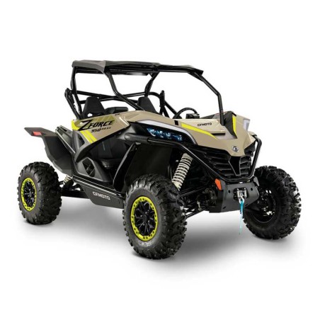
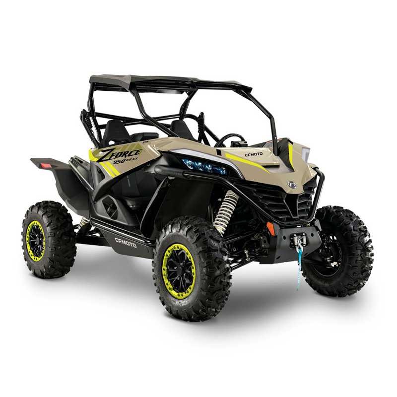
CFMOTO ZFORCE 950/1000 from 2022 Service Manual
Documentation details: Edition item: CF1000SU-E, CF1000SZ-E, CF1000SU-D, CF1000SZ-D, CF1000UTR-C,(5BYV-00WX01-12) SM-20220114
Key topics: 1.7 Engine Break-in; 1.9 Fuel, Engine Oil, Transmission Oil and Coolant; 5.5.5 Cylinder Body; 6.14 Battery Box; 01 SAFETY INFORMATION.
Manual contents
- CONTENTS:
- 01 SAFETY INFORMATION
- - 1.1 Service Manual
- - 1.2 Safety Tips
- - 1.3 Hazardous Level and Symbol
- - 1.4 Operation Notice
- - 1.5 General Precaution
- - 1.5.1 Avoid Carbon Monoxide Poisoning
- - 1.5.2 Avoid Corrosion Injury by Electrolyte
- - 1.5.3 Avoid Injury
- - 1.5.4 Avoid Scald
- - 1.5.5 Avoid Toxic Coolant
- - 1.5.6 Avoid Explode and Fire
- - 1.5.7 Operational Safety
- - 1.6 Cautions for Removal and Installation
- - 1.7 Engine Break-in
- - 1.8 Warranty
- - 1.9 Fuel, Engine Oil, Transmission Oil and Coolant
- - 1.10 Caption
- 02 SPECIFICATIONS/VEHICLE DATA
- - 2.1 Unit Conversion Table and Symbols
- - 2.2 Identification Number Locations
- - 2.3 Main Specifications
- - 2.4 Specifications for Service
- - 2.5 Fastener Torque Tables
- - 2.6 Grease and Sealant
- - 2.7 Service Products
- - 2.8 Service Tools
- 03 MAINTENANCE INFORMATION
- - 3.1 Maintenance Schedule
- - 3.1.1 Pre-Ride Maintenance Checklist
- - 3.1.2 Break-In Maintenance Checklist
- - 3.3.1 Periodic Maintenance Schedule
- 04 CVT SYSTEM
- - 4.1 CVT Special Tool
- - 4.2 CVT Removal
- - 4.2.1 Preliminary Work
- - 4.2.2 CVT Case Cover Removal
- - 4.2.3 CVT Drive Pulley, Driven Pulley and Drive Belt Removal
- - 4.3 CVT Parts Inspection
- - 4.3.1 CVT Case Cover Inspection
- - 4.3.2 Drive Belt Inspection
- - 4.3.3 Drive Pulley Inspection
- - 4.3.4 Driven Pulley Inspection
- - 4.4 CVT Installation
- - 4.4.1 Drive Pulley, Driven Pulley and Drive Belt Installation
- - 4.4.2 CVT Case Cover Installation
- - 4.4.3 CVT Surrounding Parts Installation
- 05 ENGINE
- - 5.1 Special Tools for Engine
- - 5.2 Engine Removal
- - 5.2.1 Preliminary Work
- - 5.2.2 Removal
- - 5.3 Engine Air Inlet/Outlet System
- - 5.3.1 Air Filter
- - 5.3.1.1 Removal
- - 5.3.1.2 Air Filter Parts Inspection
- - 5.3.1.3 Air Filter Installation
- - 5.3.2 Engine Inlet Pipe
- - 5.3.3 Air Exhaust System
- - 5.3.3.1 Muffler Assy Removal
- - 5.3.3.2 Muffler Parts Inspection
- - 5.3.3.3 Muffler Assy Assembly
- - 5.3.3.4 Air Filter Element
- - 5.4 Engine Disassembly
- - 5.4.1 CVT
- - 5.4.2 Engine Oil and Transmission Oil Drain
- - 5.4.3 Thermostat and Thermostat Seat
- - 5.4.4 Oil Cooler
- - 5.4.5 First Cylinder TDC Adjustment
- - 5.4.6 First Cylinder Tensioner
- - 5.4.7 First Cylinder Head Cover
- - 5.4.8 First Cylinder Head
- - 5.4.9 Second Cylinder TDC Adjustment
- - 5.4.10 Second Cylinder Tensioner
- - 5.4.11 Second Cylinder Head Cover
- - 5.4.12 Second Cylinder Head
- - 5.4.13 Air Bag
- - 5.4.14 Oil Filter
- - 5.4.15 Water Pump
- - 5.4.16 Starter Motor
- - 5.4.17 MAG Crankcase Cover
- - 5.4.18 Magneto Rotor
- - 5.4.19 Starter Dual Gear
- - 5.4.20 Breather Parts
- - 5.4.21 Oil Pump Idle Gear and Water Pump Idle Gear
- - 5.4.22 Oil Pump
- - 5.4.23 First Cylinder Timing Chain
- - 5.4.24 Second Cylinder Timing Chain
- - 5.4.25 Gearshift Assy
- - 5.4.26 First Cylinder and Piston
- - 5.4.27 Second Cylinder and Piston
- - 5.4.28 Crankcase Disassembly
- - 5.4.29 Crankshaft Connecting Rod Assy and Main Shaft
- - 5.4.30 Countershaft Assy, Shift Fork and Shift Drum
- - 5.5 Engine Parts Inspection
- - 5.5.1 Cylinder Head Cover
- - 5.5.2 Cylinder Head
- - 5.5.3 Parts Inspection
- - 5.5.4 Cylinder Head Assy
- - 5.5.5 Cylinder Body
- - 5.5.6 Timing Chain Tensioner
- - 5.5.7 Piston
- - 5.5.8 Timing Chain
- - 5.5.9 Tension Plate, Chain Guide and Chain Guard
- - 5.5.10 Shift Gear Assy
- - 5.5.11 Gearshift Cover
- - 5.5.12 Water Pump Assy
- - 5.5.13 Oil Filter
- - 5.5.14 Overriding Clutch
- - 5.5.15 Magneto Rotor
- - 5.5.16 Magneto Stator
- - 5.5.17 Starter Dual Gear
- - 5.5.18 Oil Pump Gear and Oil Pump Idle Gear
- - 5.5.19 Oil Pump Assy
- - 5.5.20 Breather and Breather Idle Gear
- - 5.5.21 Driven Gear
- - 5.5.22 Crankshaft Assy
- - 5.5.23 Transmission Assy
- - 5.5.24 Reverse Intermediate Gear
- - 5.5.25 Drive Bevel Gear
- - 5.5.26 Driven Bevel Gear
- - 5.5.27 Front Output Shaft
- - 5.5.28 Thermostat and Water Temperature Sensor
- - 5.5.29 MAG Crankcase Cover
- - 5.5.30 MAG Crankcase
- - 5.5.31 PTO Crankcase
- - 5.5.32 CVT Case
- - 5.5.33 Oil Cooler Assy
- - 5.5.34 Thermostat Seat and Water Pipe
- - 5.5.35 Water Pipe Bracket and Oil Cooler Pipes
- - 5.6 Engine Assembly
- - 5.6.1 Countershaft Assy, Shift Fork Assy and Shift Drum Assy
- - 5.6.2 Drive Bevel Gear Assy
- - 5.6.3 Crankshaft Connecting Rod Assy
- - 5.6.4 Bevel Gear Washer Adjustment
- - 5.6.5 First Cylinder Body and Piston
- - 5.6.6 Second Cylinder Body and Piston
- - 5.6.7 Gearshift Assy
- - 5.6.8 First Cylinder Timing Chain
- - 5.6.9 Second Cylinder Timing Chain
- - 5.6.10 Oil Pump
- - 5.6.11 Oil Pump Idle Gear and Water Pump Idle Gear
- - 5.6.12 Breather Assy
- - 5.6.13 Starter Dual Gear
- - 5.6.14 Magneto Rotor
- - 5.6.15 MAG Crankcase Cover
- - 5.6.16 Starter Motor
- - 5.6.17 Water Pump
- - 5.6.18 Oil Filter
- - 5.6.19 Air Bag
- - 5.6.20 First Cylinder TDC Adjustment
- - 5.6.21 First Cylinder Head Assy
- - 5.6.22 First Cylinder Tensioner
- - 5.6.23 First Cylinder Valve Clearance Adjustment
- - 5.6.24 First Cylinder Head Cover
- - 5.6.25 Second Cylinder TDC Adjustment
- - 5.6.26 Second Cylinder Head Assy
- - 5.6.27 Second Cylinder Tensioner
- - 5.6.28 Second Cylinder Valve Clearance Adjustment
- - 5.6.29 Second Cylinder Head Cover
- - 5.6.30 Plug Cover and RPM Sensor
- - 5.6.31 Oil Cooler Assy
- - 5.6.32 Thermostat and Thermostat Seat
- - 5.6.33 Drain Bolt
- - 5.6.34 Oil Dipstick
- - 5.6.35 CVT Case
- - 5.7 Engine Installation
- - 5.8 Cooling System
- - 5.8.1 Sealing Inspection
- - 5.8.2 Coolant Replacement
- - 5.9 Lubrication System
- - 5.9.1 Engine Oil Level Inspection
- - 5.9.2 Engine Oil Replacement
- - 5.9.3 Transmission Oil Inspection
- - 5.9.4 Transmission Oil Replacement
- - 5.9.5 Engine Oil Pressure Inspection
- - 5.10 Fuel System
- - 5.10.1 Fuel System Removal
- - 5.10.2 Fuel System Inspection
- - 5.10.3 Fuel System Installation
- 06 BODY COVERING PARTS
- - 6.1 Seat
- - 6.2 Front Top Cover
- - 6.2.1 Front Service Cover
- - 6.2.2 Seat Lower Fender
- - 6.2.3 Passenger Seat Lower Fender
- - 6.2.4 Seat Middle RH Protection Plate
- - 6.2.5 Middle Protection Cover
- - 6.2.6 Middle Panel
- - 6.3 Lock Hook
- - 6.3.1 Dashboard Panel
- - 6.3.2 Storage Box Cover Assy
- - 6.4 Front Wheel Fender (Status 1)
- - 6.5 Front Wheel Fender (Status 2)
- - 6.6 Damping Deco Guard
- - 6.7 Headlight Panel
- - 6.8 Cab
- - 6.8.1 Rear View Mirror
- - 6.8.2 Cab
- - 6.9 Side Door (Status 1)
- - 6.10 Side Door (Status 2)
- - 6.11 Ventilation Grid
- - 6.12 Winch Deco Cover
- - 6.13 Front Inner Fixed Plate
- - 6.14 Battery Box
- - 6.15 Front Fender
- - 6.16 Rear Fender (Status 1)
- - 6.17 Rear Fender (Status 2)
- - 6.18 CVT Deco Cover Assy
- - 6.18.1 CVT Inner Deco Cover
- - 6.18.2 Rear Rack Cover Plate
- - 6.19 Rear Side Protection Plate
- - 6.20 Seat LH Protection Plate
- - 6.21 Seat Rear Protection Plate
- - 6.21.1 ECU Cover
- - 6.21.2 Seat Rear Service Plate
- - 6.21.3 Seat Rear Protection Plate
- - 6.21.4 Rear Ventilation Plate
- - 6.22 Seat Front Protection Plate
- - 6.23 Foot Pedal
- - 6.24 Front Side Protection Plate
- - 6.25 Air Filter Cover
- - 6.26 Rear Cargo Box Base Plate
- - 6.26.1 Rear Cargo Box Deco Cover
- - 6.27 Rear Rack Assy
- 07 POWERTRAIN
- - 7.1 CV Drive Shaft
- - 7.2 CV Drive Shaft Service
- - 7.2.1 CV Drive Shaft Inspection
- - 7.2.1.1 Shaft Cage Dust Boot
- - 7.3 Drive Shaft
- - 7.3.1 Front Drive Shaft Removal
- - 7.3.2 Rear Drive Shaft Removal
- - 7.3.3 Drive Shafts Inspection
- - 7.3.4 Drive Shaft Installation
- - 7.3.4.1 Front Drive Shaft Installation
- - 7.3.4.2 Rear Drive Shaft Installation
- - 7.4 Front and Rear Gear Case
- - 7.4.1 Maintenance Information
- - 7.4.2 Inspection and Maintenance
- - 7.5 Front Gear Case
- - 7.5.1 Front Gear Case Disassembly
- - 7.5.2 Front Gear Case Input Shaft Disassembly
- - 7.5.3 Differential Disassembly
- - 7.5.4 Parts Inspection
- - 7.6 Front Gear Case Assembly
- - 7.6.1 Differential Assembly
- - 7.6.2 Front Gear Case Drive Bevel Gear Assembly
- - 7.6.3 Spline Bushing Assembly
- - 7.6.4 Front Gear Case Motor Installation
- - 7.6.5 Gear Case Cover Installation
- - 7.7 Rear Gear Case (Version 1)
- - 7.8 Rear Gear Case Disassembly (Version 1)
- - 7.8.1 Rear Gear Case Cover
- - 7.8.2 Driven Bevel Gear Assy
- - 7.8.3 Drive Bevel Gear Assy
- - 7.9 Rear Gear Case (Version 2)
- - 7.10 Rear Gear Case Disassembly (Version 2)
- - 7.10.1 Rear Gear Case Cover
- - 7.10.2 Differential Assy
- - 7.10.3 Drive Bevel Gear Assy
- - 7.10.4 Rear Gear Case Inspection
- - 7.10.4.1 Installation
- 08 BRAKE SYSTEM
- - 8.1 Brake Caliper
- - 8.2 Brake Disc and Mounting Seat
- - 8.3 Brake Fluid
- - 8.4 Brake Pedal
- - 8.5 Parking Brake
- 09 SUSPENSION SYSTEM
- - 9.1 Tire
- - 9.2 Rim Bracket
- - 9.3 Shock Absorber
- - 9.4 Front Swing Arm
- - 9.5 Rear Suspension
- - 9.5.1 Rear Swing Arm Rod
- - 9.5.2 Rear Sway Bar
- - 9.5.3 Rear Swing Arm
- 10 STEERING SYSTEM
- - 10.1 Steering System
- - 10.1.1 Steering Wheel
- - 10.1.2 Steering Column and EPS
- - 10.1.3 Steering Motor
- - 10.2 Gearshift Assy
- - 10.3 EPS
- - 10.3.1 EPS Failure Code Table
- - 10.3.2 EPS Fault Analysis and Troubleshooting
- 11 COOLING SYSTEM
- - 11.1 Cooling System
- - 11.2 Fan Motor
- - 11.3 Radiator Fan Inspection
- - 11.4 Cooling System Sealing
- - 11.5 Coolant
- 12 ELECTRICAL SYSTEM
- - 12.1 Diagnosis Tool
- - 12.2 Signal and Illumination System
- - 12.2.1 Battery
- - 12.2.2 Battery Charging
- - 12.2.3 Charging Voltage Inspection
- - 12.3 Earth Wire Inspection
- - 12.4 Fuse
- - 12.5 Light Maintenance Information
- - 12.6 Illumination Inspection
- - 12.7 Light Removal and Installation
- - 12.7.1 Headlight Assembly
- - 12.7.2 Tail Light Assembly
- - 12.8 Horn
- - 12.9 Switches
- - 12.10 Ignition Switch Lock
- - 12.11 Winch Control Switch
- - 12.12 Body Control Module (BCM)
- - 12.13 Charging System
- - 12.13.1 Charging system wiring
- - 12.13.2 Starter Relay
- - 12.13.3 Start Auxiliary Relay, Fuel Pump Relay
- - 12.13.4 Engine Starting Note
- - 12.14 EFI System
- - 12.14.1 EFI Structure
- - 12.14.2 Sensors
- - 12.14.3 ECU
- - 12.14.4 Actuators
- - 12.14.5 EFI System Maintenance Notice
- - 12.15 Structure and Performance of EFI Parts
- - 12.15.1 ECU
- - 12.15.2 Throttle Assembly
- - 12.15.3 T-MAP
- - 12.15.4 Coolant Temp. Sensor
- - 12.15.5 Oxygen Sensor
- - 12.15.6 Crankshaft Position Sensor
- - 12.15.7 Speed Sensor
- - 12.15.8 Gear Sensor
- - 12.15.9 Fuel Pump
- - 12.15.10 Fuel Injector
- - 12.15.11 Ignition Coil
- - 12.16 Electrical Throttle Pedal
- - 12.17 EFI Self-diagnosis
- - 12.17.1 Malfunction Indicating Lamp (MIL)
- - 12.17.2 Diagnosis Tool and Connector
- - 12.18 Fault Diagnosis
- - 12.18.1 Engine Body
- - 12.19 Fault Code Table
- - 12.19.1 Diagnosis by Fault Code
- - 12.19.2 Fault Diagnosis by Engine Problems