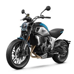
Cfmoto 300SR 300SS from 2023 — 300SR / 300SS Service & Repair Manual
This download contains workshop and maintenance procedures for the CF300 variants explicitly listed in the source for Cfmoto 300SR 300SS from 2023. The original index is reproduced in full and in order; listed systems do not imply additional, unlisted repair procedures.
Additional details from the original listing
- - Edition Item: 300SR 300SS (6KNV-00WX01-8100)SM-20230724.pdf
- - 300SR:CF300-5 CF300-5B CF300-5F CF300-5BF
- - 300SS:CF300-5US CF300-5BUS
Listed variants: 300SR: CF300-5, CF300-5B, CF300-5F and CF300-5BF; 300SS: CF300-5US and CF300-5BUS, as stated in the source description.
Selected indexed topics: 02 MAINTENANCE INFORMATION; 01 GENERAL INFORMATION; 1.1 Operation Cautions.
Original technical index
- 01 GENERAL INFORMATION
- - 1.1 Operation Cautions
- - 1.2 Disassembly and Assembly Cautions
- - 1.3 VIN and EIN Location
- - 1.4 Fuel Evaporation System Schematic Diagram
- 02 MAINTENANCE INFORMATION
- - 2.1 Maintenance before Operation
- - 2.2 Break-in Maintenance Schedule
- - 2.3 Periodic Maintenance Schedule
- 03 TECHNICAL INFORMATION
- - 3.1 Main Parameters of the Vehicle
- - 3.2 Engine Main Parameters
- - 3.3 Maintenance Parameter Table
- - 3.3.1 Front Wheel
- - 3.3.2 Rear Wheel
- - 3.3.3 Brake System
- - 3.3.4 Lighting, Dashboard and Switches
- - 3.3.5 Valve Train&Cylinder Head
- - 3.3.6 Lubrication System
- - 3.3.7 Cylinder, Piston, Piston Ring and Connecting Rod
- - 3.3.8 Clutch and Transmission
- - 3.3.9 Cooling System
- - 3.3.10 Air Inlet System
- - 3.3.11 Electrical System
- - 3.4 Tighten Torque
- - 3.4.1 Tighten Torque Table for Vehicle
- - 3.4.2 Tighten Torque Table for Engine
- - 3.5 Lubrication Requirements
- - 3.5.1 Complete Vehicle Lubrication Requirements
- - 3.5.2 Lubrication Requirements for Engine
- 04 SEAT
- - 4.1 Seat
- 05 BODY COVERING PARTS
- - 5.1 Rear View Mirror and Front Windshield
- - 5.2 Fuel Tank Guard Assembly
- - 5.2.1 Fuel Tank Guard Disassembly
- - 5.3 LH Guard of Headlight
- - 5.4 Front LH Panel and LH Spoiler Assembly
- - 5.4.1 Front LH Panel and LH Spoiler Assembly Disassembly
- - 5.5 Front RH Panel and RH Spoiler Assembly
- - 5.5.1 Front RH Panel and RH Spoiler Assembly Disassembly
- - 5.6 Seat Lower Deco Guard and Tail Guard Assembly
- - 5.6.1 Seat Lower Deco Guard and Tail Guard Assembly Disassembly
- - 5.7 LH Panel
- - 5.8 RH Panel
- - 5.9 Dashboard and Dashboard Guard Assembly
- - 5.9.1 Dashboard and Dashboard Guard Assembly Disassembly
- - 5.10 Fuel Tank LH Front Panel
- - 5.11 LH Front Inner Panel
- - 5.12 RH Front Inner Panel
- - 5.13 Front Lower Fender
- - 5.14 Engine Lower Guard
- - 5.14.1 Engine Lower Guard Disassembly
- - 5.15 LH Middle Deco Cover
- - 5.16 RH Middle Deco Cover
- - 5.17 Small Sprocket Guard
- - 5.18 Headlight Assembly
- - 5.18.1 Headlight Assembly Disassembly
- - 5.19 Rear Fender Upper and Lower Body Assembly
- - 5.19.1 Rear Fender Upper and Lower Body Assembly Disassembly
- - 5.20 Rear Fender and Tail Light Assembly
- - 5.20.1 Rear Fender and Tail Light Assembly Disassembly
- - 5.21 Frame Block
- - 5.21.1 Frame LH Block
- - 5.21.2 Frame RH Block
- - 5.22 Front Fender Assembly
- - 5.22.1 Front Fender Assembly Disassembly
- - 5.23 Canister Deco Guard
- 06 FUEL TANK
- - 6.1 Fuel Tank
- 07 LIGHTS, DASHBOARD AND SWITCHES
- - 7.1 Maintenance Information
- - 7.1.1 Operation Caution
- - 7.1.2 Inspection Standard
- - 7.2 Lights Troubleshooting
- - 7.3 Ignition Lock Assembly
- - 7.4 Front Brake Light Switch
- - 7.5 Handlebar Switch
- - 7.5.1 LH Handlebar Switch
- - 7.5.2 RH Handlebar Switch
- - 7.6 Fuel Level Sensor
- - 7.7 Battery
- - 7.8 Ground Wire
- - 7.9 T-BOX
- 08 ELECTRICAL SYSTEM
- - 8.1 Service Tool
- - 8.2 Charging System
- - 8.2.1 Charging Diagram
- - 8.2.2 Magneto Coil Resistance
- - 8.2.3 MAG Non-loaded Performance
- - 8.2.4 Regulator
- - 8.3 EFI System
- - 8.3.1 EFI Structure
- - 8.3.1.1 Sensors
- - 8.3.1.2 ECU
- - 8.3.1.3 Actuators
- - 8.3.2 EFI System Maintenance Notice
- - 8.3.3 Structure and Performance of EFI Parts
- - 8.3.3.1 ECU
- - 8.3.3.2 Throttle Bodyy
- - 8.3.3.3 T-MAP
- - 8.3.3.4 Water Temp. Sensor
- - 8.3.3.5 Oxygen Sensor
- - 8.3.3.6 Trigger
- - 8.3.3.7 Fuel Pump
- - 8.3.3.8 Fuel Injector
- - 8.3.3.9 Idle Stepping Motor
- - 8.3.3.10 Ignition coil
- - 8.3.4 Self-diagnosis
- - 8.3.4.1 MIL
- - 8.3.4.2 Fault Code
- - 8.4 Fault Diagnosis and Treatment
- - 8.4.1 Engine Body
- - 8.5 Trouble Diagnosis In Accordance With Engine Error
- 09 COOLING SYSTEM
- - 9.1 Cooling System Diagram
- - 9.2 Cooling System
- - 9.2.1 Cooling Pipe
- - 9.3 Coolant
- - 9.4 Inspection for Cooling Cycle Seal
- - 9.5 Fan Moto Assembly
- - 9.6 Clean and Inspection for Radiator Assembly
- - 9.6.1 Inspect Water Inlet Pipe and Outlet Pipe
- 10 MUFFLER
- - 10.1 Muffler Assembly
- - 10.1.1 Muffler Assembly Inspection and Repairment
- 11 WHEELS AND BRAKE SYSTEM
- - 11.1 Front Wheel
- - 11.2 Rear Wheel- Double Swing Arm
- - 11.3 Rear Wheel- Single Swing Arm
- - 11.3.1 Sliding Bearing Replacement
- - 11.4 Footrest Bracket
- - 11.4.1 LH Front Footrest Bracket
- - 11.4.2 RH Front Footrest Bracket
- - 11.5 MAB Hydraulic Brake Assembly- Double Swing Arm
- - 11.5.1 Sprocket Guard
- - 11.5.2 Rear Brake Master Cylinder Assembly
- - 11.5.3 Remove MAB Hydraulic Brake Assembly
- - 11.5.3.1 MAB Execution Unit
- - 11.5.3.2 Rear Brake Pump and Rear Brake Caliper Assembly
- - 11.5.3.3 Hand Brake Pump Assembly
- - 11.5.3.4 Front Brake Caliper Assembly
- - 11.6 MAB Hydraulic Brake Assembly- Single Swing Arm
- - 11.6.1 Rear Brake Master Cylinder Assembly
- - 11.6.2 Remove MAB Hydraulic Brake Assembly
- - 11.6.2.1 MAB Execution Unit
- - 11.6.2.2 Rear Brake Pump
- - 11.6.2.3 Rear Brake Caliper
- - 11.6.2.4 Hand Brake Pump Assembly
- - 11.6.2.5 Front Brake Caliper
- - 11.7 Wheel Inspection
- - 11.7.1 Sprocket Seat (Double Swing Arm)
- - 11.7.2 Tire Pressure
- - 11.7.3 Tire Appearance
- - 11.7.4 Wheel Bearing
- - 11.7.5 Rim
- - 11.8 Brake System Inspection
- - 11.8.1 Front Master Cylinder Inspection
- - 11.8.2 Brake Caliper and Brake Disc Inspection
- - 11.8.3 Rear Brake Master Cylinder Inspection
- - 11.8.4 Brake Hose Inspection
- - 11.9 Free Play
- - 11.9.1 Front Brake Lever Free Play
- - 11.9.2 Rear Brake Pedal Free Play
- 12 SHOCK ABSORBER AND REAR FORK
- - 12.1 Front Suspension Assembly Diagram
- - 12.2 Front Shock Absorber
- - 12.3 Chain
- - 12.4 Rear Suspension Assembly Diagram- double swing arm
- - 12.5 Rear Shock Absorber- Double Swing Arm
- - 12.6 Rear Fork- Double Swing Arm
- - 12.6.1 Chain Guard
- - 12.7 Rear Suspension Assembly Diagram- single swing arm
- - 12.8 Rear Shock Absorber- Single Swing Arm
- - 12.9 Rear Fork- Single Swing Arm
- - 12.9.1 Chain Guard
- - 12.10 Drive Chain Inspection
- - 12.10.1 Chain Looseness Adjustment - Double Swing Arm
- - 12.10.2 Chain Looseness Adjustment - Single Swing Arm
- - 12.11 Front Shock Absorber Inspection
- - 12.12 Rear Shock Absorber Inspection
- - 12.13 Rear Shock Absorber Adjustment
- 13 ENGINE
- - 13.1 Preparation Instruction
- - 13.2 Maintenance Information
- - 13.2.1 Engine Appearance
- - 13.2.2 General Prevention Measures
- - 13.2.3 Fuel and Engine Oil Selection
- - 13.2.4 Engine Break-in
- - 13.2.5 Engine Technical Information
- - 13.2.6 Service Information
- - 13.2.7 Tighten Torque Chart
- - 13.2.8 Service Tools
- - 13.2.9 Engine Consumption Materials & Assembling Materials
- - 13.3 Engine Removal
- - 13.4 Engine Installation
- - 13.5 Engine Disassembly
- - 13.5.1 Engine Fixing
- - 13.5.2 Draining the engine oil
- - 13.5.3 Secondary Gulp Valve Removal (Euro 5 status)
- - 13.5.4 Oil Filter Removal
- - 13.5.5 RH Side Cover Removal
- - 13.5.6 Water Pump Impeller Removal
- - 13.5.7 TDC Adjustment
- - 13.5.8 Clutch Removal
- - 13.5.9 Output Gear Removal
- - 13.5.10 Relief Valve Removal
- - 13.5.11 Oil Pump Removal
- - 13.5.12 Gearshift Lever, Gear Position Part and Shift Drum Cam Removal
- - 13.5.13 Starter Motor Removal
- - 13.5.14 LH Side Cover Removal
- - 13.5.15 Dual Gear, Middle Gear and Magneto Rotor Removal
- - 13.5.16 Valve System Removal
- - 13.5.17 Cylinder Head, Cylinder Body Removal
- - 13.5.18 Piston, Piston Pin Removal
- - 13.5.19 Gear Contactor and Oil Strainer Removal
- - 13.5.20 RH Crankcase Removal
- - 13.5.21 Gearshift Assembly Removal
- - 13.5.22 Crankshaft Removal
- - 13.5.23 Bearing 6207 Removal
- - 13.5.24 Cylinder Head Assembly Removal
- - 13.5.25 Magneto Stator Removal
- - 13.6 Inspection and Assembly
- - 13.6.1 RH Crankcase
- - 13.6.2 LH Crankcase
- - 13.6.3 Cylinder Head Assembly
- - 13.6.4 Valve System
- - 13.6.5 Cylinder Body
- - 13.6.6 Crankshaft and Piston
- - 13.6.7 Oil Pump
- - 13.6.8 Water Pump Assembly
- - 13.6.9 Clutch Control Shaft Assembly
- - 13.6.10 Magneto Assembly
- - 13.6.11 Start System
- - 13.6.12 Clutch Assembly
- - 13.6.13 Gearshift Assembly
- - 13.6.14 Main Shaft, Counter Shaft
- - 13.7 Engine Assembly
- - 13.7.1 Preparation
- - 13.7.2 Crankshaft, Balance Shaft Installation
- - 13.7.3 Main Shaft and Counter Shaft Installation
- - 13.7.4 Shift Drum, Shift Fork and Shift Shaft Installation
- - 13.7.5 RH Crankcase Installation
- - 13.7.6 Oil Strainer and Gear Position Sensor Installation
- - 13.7.7 Gearshift Assembly Installation
- - 13.7.8 Piston Installation
- - 13.7.9 Cylinder Body Installation
- - 13.7.10 Timing Chain, Chain Guide, Tensioner Installation
- - 13.7.11 Oil Pump Assembly Installation
- - 13.7.12 Relief Valve Installation
- - 13.7.13 Output Gear Installation
- - 13.7.14 Clutch Assembly Installation
- - 13.7.15 Magneto Rotor Installation
- - 13.7.16 Dual Gear and Starter Middle Gear Installation
- - 13.7.17 LH Side Cover Installation
- - 13.7.18 Cylinder Head Installation
- - 13.7.19 Starter Motor Installation
- - 13.7.20 RH Side Cover Installation
- - 13.7.21 Oil Filter Installation
- - 13.7.22 Cylinder Head Cover Installation
- - 13.7.23 Secondary Gulp Valve Installation (Euro 5 Status)
- - 13.7.24 Drain Bolt Installation
- - 13.8 Air Intake System
- - 13.9 Air Intake System (Euro 5 Status)
- - 13.10 Lubrication System
- - 13.11 Engine Oil Addition and Oil Pressure Measurement
- 14 HANDLEBAR AND TRIPLE CLAMPS
- - 14.1 Clutch Lever
- - 14.2 LH Handlebar Switch
- - 14.3 LH Balance Block, LH Hand Grip
- - 14.4 RH Handlebar Switch
- - 14.5 Throttle Cable
- - 14.6 RH Balance Block, RH Hand Grip
- - 14.7 Handlebar Inspection
- - 14.7.1 Throttle Cable Free Play
- - 14.7.2 Clutch Handle Clearance Inspection
- - 14.7.3 Handlebar Interference Inspction
- - 14.8 Front Suspension Assembly Diagram
- - 14.9 Upper Triple Clamp Assembly
- - 14.10 Lower Triple Clamp, Front Fork Pipe