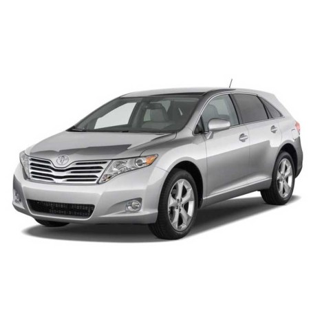
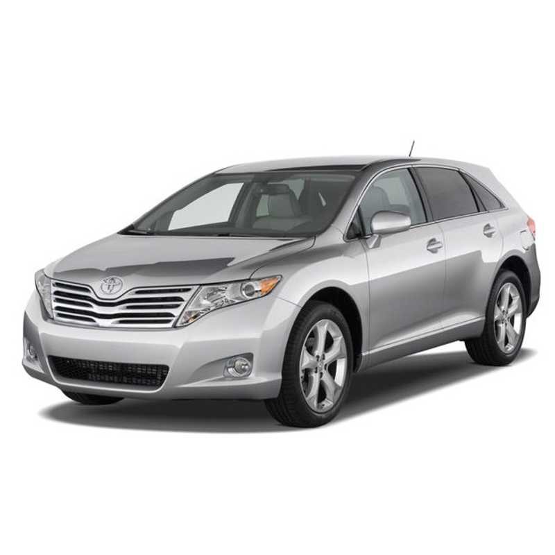
Toyota Venza 2009-2015 — Electrical Wiring Diagrams
This download provides electrical wiring, circuit schematics and the component-related information listed in the index for Toyota Venza 2009-2015. The technical index below is retained from the original product listing; headings and listed systems do not imply additional unlisted procedures.
Document details from the original listing
- MODELS CODE: AGV10, AGV15
- ENGINES CODE: 1AR-FE
Indexed topics include: ABS , Hill-Start Assist Control , TRC , VSC; OVERALL ELECTRICAL WIRING DIAGRAMS; RELAY LOCATIONS.
Original technical index
- ELECTRICAL WIRING DIAGRAMS
- ABS , Hill-Start Assist Control , TRC , VSC
- Air Conditioner
- Automatic Glare-Resistant EC Mirror with Compass
- Automatic Light Control , Light Auto Turn Off System
- AWD
- Back Door Closer , Back Door Opener
- Back-Up Light
- Cooling Fan
- Combination Meter , Multi Display
- Charging
- Door Lock Control
- DLC3
- Cruise Control , ECT and A/T Indicator , Engine Control
- Engine Immobiliser System
- EPS
- Front Fog Light , Rear Fog Light
- Front Window Deicer
- Front Wiper and Washer
- Ground Point
- Headlight Beam Level Control
- Headlight Cleaner
- Headlight
- Horn
- Interior Light
- Ignition
- Key Reminder
- Mirror Heater , Remote Control Mirror
- Multiplex Communication System
- Back Door Opener , Power Back Door
- Power Outlet
- Power Source
- Power Seat
- Power Seat
- OVERALL ELECTRICAL WIRING DIAGRAMS
- Power Source
- Mul tipl ex Communication System (CAN)
- Engine Immobil iser System (w/ Smart Entry & Start System), Smart Entry & Start System, Starting (w/ Smart Entry & Start System), Steering Lock (w/ Smart Entry & Start System) and Wirel ess Door Lock Control (w/ Smart Entry & Start System)
- Starting (w/o Smart Entry & Start System)Charging
- Ignition
- Engine Control
- Engine ControlCruise Control
- ECT and A/T Indicator
- Engine Immobil iser System (w/o Smart Entry & Start System) DLC3
- Turn Signal and Hazard Warning Light
- Back–Up LightStop Light
- Front Wiper and Washer
- Rear Wiper and Washer
- Sl iding Roof
- Power Out l et
- ABS, Hi l l –Start Assi st Control , TRC and VSC
- SRS
- Seat Bel t Warning
- EPS
- AWD
- Headl ight Beam Level Control
- Headl ight Cl eaner
- Power Back Door
- Back Door Cl oser
- Power Seat (Driver's Seat)
- Power Seat (Front Passenger's Seat)
- Seat Heater
- Mirror Heater and Remote Control Mirror
- Front Window Deicer
- HornShift Lock
- Multi Display
- Audio System (13 Speaker Navigation Receiver Type), Navigation System (13 Speaker Navigation Receiver Type) and Parking Assist (Rear View Monitor) (13 Speaker Navigation Receiver Type)
- Audio System (13 Speaker Radio & Displ ay Receiver Type), Navigation System (13 Speaker Radio & Displ ay Receiver Type) and Parking Assist (Rear View Monitor) (13 Speaker Radio & Displ ay Receiver Type)
- Audio System (6 Speaker) and Parking Assist (Rear View Monitor) (6 Speaker)
- Combination Meter
- Cool ing FanRear Window Defogger
- Air Conditioner
- COMPONENTS LOCATIONS
- Antenna in Antenna
- Ground Points in Body
- Position of Parts in Body
- Wire and Wire in Body
- Position of Parts in Engine Compartment
- Wire and Wire , Ground Points in Engine Compartment
- Ground Points in Instrument Panel
- Position of Parts in Instrument Panel
- Wire and Wire in Instrument Panel
- Wire and Wire , Ground Points in Seat
- Position of Parts in Seat
- RELAY LOCATIONS
- [Body]
- [Seat]
- [Engine Compartment]
- [Instrument Panel]
- [Body]
- [Seat]
- [Driver Side J/B Assembly Inner Circuit]
- [Engine Room R/B and Engine Room J/B Inner Circuit]
- [Junction Connector (CAN No. 1) Inner Circuit]
- [Junction Connector (CAN No. 2) Inner Circuit]
- [Junction Connector (CAN No. 3) Inner Circuit]