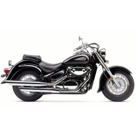
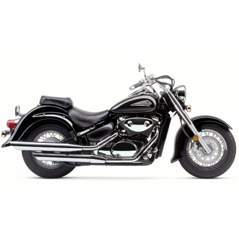
Suzuki Intruder VL800 (2001-2009) - Repair, Service Manual, Wiring Diagrams and Owners Manual
Digital technical documentation with sections on SERVICE MANUAL, - How To Use This Manual, - To Locate What You Are Looking For:. Review the complete contents below for the systems and procedures covered.
Manual contents
- SERVICE MANUAL
- Foreword
- - How To Use This Manual
- - To Locate What You Are Looking For:
- - Component Parts And Work To Be Done
- - Symbol
- 01 General Information
- - Warning/Caution/Note
- - General Precautions
- - Suzuki Vl800k1 (2001-Model)
- - Serial Number Location
- - Fuel, Oil And Engine Coolant Recommendation
- - Fuel
- - Engine Oil
- - Gear Oil (Final Drive Gear Oil)
- - Brake Fluid
- - Front Fork Oil
- - Engine Coolant
- - Break-In Procedures
- - Cylinder Identification
- - Information Labels
- - Specifications
- - Country And Area Codes
- 02 Periodic Maintenance
- - Periodic Maintenance Schedule
- - Periodic Maintenance Chart
- - Lubrication Points
- - Maintenance And Tune-Up Procedures
- - Air Cleaner
- - Spark Plug
- - Valve Clearance
- - Engine Oil And Oil Filter
- - Fuel Hose
- - Engine Idle Speed
- - Pair (Air Supply) System
- - Throttle Cable Play
- - Clutch
- - Cooling System
- - Final Gear Oil
- - Brake
- - Tires
- - Steering
- - Front Fork
- - Rear Suspension
- - Exhaust Pipe Bolt And Nut
- - Chassis Bolts And Nuts
- - Compression Pressure Check
- - Oil Pressure Check
- 03 Engine
- - Engine Components Removable With Engine In Place
- - Engine Removal And Installation
- - Engine Removal
- - Engine Installation
- - Engine Disassembly
- - Engine Components Inspection And Servicing
- - Cylinder Head Cover
- - Camshaft
- - Cam Chain Tensioner And Guide
- - Cylinder Head
- - Piston
- - Conrod/Crankshaft
- - Clutch
- - Generator/Signal Generator/ Starter Clutch
- - Oil Pump
- - Transmission
- - Gearshift Fork
- - Oil Jet
- - Crankcase
- - Engine Reassembly
- 04 Shaft Drive
- - Secondary Bevel Gears
- - Construction
- - Removal
- - Disassembly
- - Inspection
- - Secondary Gear Shims Adjustment
- - Reassembly
- - Installation
- - Final Bevel Gears
- - Construction
- - Final Gear Case Removal
- - Final Gear Case Disassembly
- - Final Gear Shims Adjustment
- - Final Gear Case Reassembly
- - Final Gear Case Installation
- 05 Fuel And Lubrication System
- - Fuel System
- - Fuel Pump
- - Fuel Tank/Fuel Valve
- - Removal
- - Inspection
- - Remounting
- - Fuel Pump
- - Removal
- - Inspection
- - Reassembly
- - Carburetor
- - Construction
- - Specifications
- - Diaphragm And Piston Operation
- - Slow System
- - Transient Enrichment System
- - Main System
- - Starter (Enricher) System
- - Float System
- - Accelerator Pump System
- - Removal
- - Disassembly
- - Carburetor Cleaning
- - Carburetor Inspection
- - Carburetor Heater And Thermo-Switch Inspection
- - Float Height Adjustment
- - Reassembly And Reinstallation
- - Lubrication System Chart
- - Pair (Air Supply) System Inspection
- 06 Cooling System
- - Engine Coolant
- - Radiator And Water Hose
- - Cooling Circuit Inspection
- - Radiator Removal
- - Radiator Cap Inspection
- - Radiator Inspection And Cleaning
- - Radiator Remounting
- - Water Hose Inspection
- - Cooling Fan
- - Inspection
- - Removal
- - Installation
- - Cooling Fan Thermo-Switch
- - Removal
- - Inspection
- - Installation
- - Engine Coolant Temperature Switch
- - Removal
- - Inspection
- - Thermostat
- - Removal
- - Inspection
- - Installation
- - Water Pump
- - Removal And Disassembly
- - Inspection
- - Reassembly And Installation
- 07 Chassis
- - Exterior Parts
- - Removal
- - Remounting
- - Front Wheel
- - Construction
- - Removal And Disassembly
- - Inspection
- - Reassembly And Remounting
- - Front Brake
- - Construction
- - Brake Pad Replacement
- - Brake Fluid Replacement
- - Caliper Removal And Disassembly
- - Caliper Inspection
- - Caliper Reassembly And Remounting
- - Brake Disc Inspection
- - Master Cylinder Removal And Disassembly
- - Master Cylinder Inspection
- - Master Cylinder Reassembly And Remounting
- - Front Fork
- - Construction
- - Removal And Disassembly
- - Inspection
- - Reassembly And Remounting
- - Steering
- - Construction
- - Removal And Disassembly
- - Inspection And Disassembly
- - Reassembly And Remounting
- - Rear Wheel
- - Construction
- - Removal
- - Disassembly
- - Inspection And Disassembly
- - Reassembly And Remounting
- - Rear Brake
- - Removal And Disassembly
- - Inspection
- - Reassembly And Remounting
- - Rear Brake Rod Removal And Disassembly
- - Reassembly And Remounting
- - Rear Suspension
- - Construction
- - Removal
- - Inspection And Disassembly
- - Reassembly
- - Remounting
- 08 Electrical System
- - Cautions In Servicing
- - Location Of Electrical Components
- - Charging System
- - Troubleshooting
- - Inspection
- - Starter System And Side-Stand/Ignition Interlock System
- - Troubleshooting
- - Starter Motor Removal And Disassembly
- - Starter Motor Inspection
- - Starter Motor Reassembly
- - Starter Relay Inspection
- - Side Stand/Ignition Interlock System Parts Inspection
- - Ignition System
- - Troubleshooting
- - Inspection
- - Speedometer
- - Removal
- - Parts Names
- - Operating Procedure
- - Inspection
- - Lamps
- - Relays
- - Switches
- - Battery
- - Specifications
- - Initial Charging
- - Servicing
- - Recharging Operation
- 09 Servicing Information
- - Troubleshooting
- - Engine
- - Carburetor
- - Shaft Drive
- - Chassis
- - Brakes
- - Electrical
- - Battery
- - Wiring Diagram (For E-02, 19 / For E-03, 28, 33 / For E-24)
- - Wire Harness, Cable And Hose Routing
- - Wire Harness Routing
- - Cable Routing
- - Fuel Hose Routing
- - Cooling Hose Routing
- - Front Brake Hose Routing
- - Battery Protector
- - Speed Sensor Lead Wire Routing
- - Special Tools
- - Tightening Torque
- - Engine
- - Secondary And Final
- - Chassis
- - Tightening Torque Chart
- - Service Data
- 10 Emission Control Information
- - Emission Control Carburetor Components
- - Evaporative Emission Control System
- - Canister Hose Routing
- - Evaporative Emission Control System Inspection
- 11 Vl800k2 ('02-Model)
- - Specifications
- - Service Data
- 12 Vl800k3 (’03-Model)
- - Specifications
- - Service Data
- - Wiring Diagram
- 13 Vl800k4 (’04-Model)
- - Specifications
- - Service Data
- - Periodic Maintenance Chart
- - Cooling Hose Routing
- - Rear Combination Light Installation
- - Wiring Diagram
- 14 Vl800k5 (’05-Model)
- - Specifications
- - Abbreviations Used In This Manual
- - Sae-To-Former Suzuki Term
- - Service Data
- - Periodic Maintenance Chart
- - Precautions In Servicing
- - Fi System Technical Features
- - Self-Diagnosis Function
- - Fail-Safe Function
- - F1 System Troubleshooting
- - Ecm Terminal
- - Sensors
- - Fuel Delivery System
- - Fuel System
- - Throttle Body
- - Emission Control Systems
- - Pair (Air Supply) System And Emission Control System Inspection
- - Evaporative Emission Control System Inspection (Only For E-33)
- - Tightening Torque
- - Wiring Harness, Cable And Hose Routing
- - Pair (Air Supply) System Diagram
- - Pair (Air Supply) System Hose Routing
- - Evap Canister Hose Routing (Only For E-33)
- - Fuel Feed Hose Routing
- - Special Tools
- 15 Vl800tk5 (’05-Model)
- - Specifications
- - Service Data
- 16 Vl800/Tk6 ('06-Model)
- - Specifications
- - Service Data
- - Special Tools
- - Conrod/Crankshaft
- - Emission Control Systems
- 17 Vl800/Tk7 (’07-Model)
- - Specifications
- - Service Data
- - Fuel Pump And Fuel Level Gauge Removal
- - Fuel Pump And Fuel Level Gauge Installation
- - Fuel Level Meter Inspection
- - Fuel Level Gauge Inspection
- - Cable Routing
- - Front Brake Hose Routing
- 18 Vl800/C/Tk9 (’09-Model)
- - Abbreviations Used In This Manual
- - Sae-To-Former Suzuki Term
- - Country And Area Codes
- - Specifications
- - Periodic Maintenance Schedule
- - Periodic Maintenance Chart
- - Maintenance And Tune-Up Procedures
- - Air Cleaner
- - Spark Plug
- - Valve Clearance
- - Engine Oil And Oil Filter
- - Throttle Cable Play
- - Throttle Valve Synchronization
- - Evaporative Emisson Control System (E-33 Only)
- - Compression Pressure Check
- - Compression Test Procedure
- - F1 System Diagnosis
- - F1 System Wiring Diagram
- - Ecm Terminal
- - Fail-Safe Function
- - Dtc Table And Defective Condition
- - Dtc Troubleshooting
- - Throttle Body
- - Construction
- - Throttle Body Removal
- - Throttle Body Disassembly
- - Throttle Body Cleaning
- - Throttle Body Inspection
- - Throttle Body Reassembly
- - Throttle Body Installation
- - Stp Sensor Adjustment
- - Tp Sensor Adjustment
- - Isc Valve Removal
- - Isc Valve Installation
- - Isc Valve Inspection
- - Isc Valve Preset And Opening Initialization
- - Throttle Valve Synchronization
- - Ignition System
- - Inspection
- - Combination Meter Inspection
- - Led (Light Emitting Diode)
- - Fuel Level Meter Inspection
- - Wiring Harness Routing
- - Cable Routing
- - Throttle Body Installation
- - Ignition Coil Installation
- - Engine Mounting
- - Muffler & Exhaust Pipe Installation
- - Pair (Air Supply) System Hose Routing
- - Rear Combination Light Installation
- - Special Tools
- - Tightening Torque
- - Engine
- - F1 System And Intake Air System
- - Service Data
- - Emission Control System
- - Exhaust Emission Control System (Pair System)
- - Evaporative Emission Control System (Only For E-33)
- - Pair (Air Supply) System Inspection
- - Heated Oxygen Sensor (Ho2s) Inspection (For E-02, 19, 24, 33)
- - Evaporative Emission Control System Inspection (Only For E-33)
- - Evap System Purge Control Solenoid Valve
- - Fuel Shut-Off Valve
- - Pair (Air Supply) System Diagram
- - Pair (Air Supply) System Hose Routing
- - Evap Canister Hose Routing (Only For E-33)
- - Wiring Diagram
- 19 Wiring Diagram
- OWNERS MANUAL