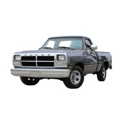
2014-2018 Index
Power Distribution, Grounding & Network Architecture
- Multi-stage power distribution schematics, central power distribution blocks, and relay mappings spanning model years 2014 through 2018.
- Ground distribution networks detailing structural earthing points, chassis grounds, and main harness routing paths.
- Computer data lines network wiring, serial communication buses, and Body Control Module (BCM) integration circuits.
Engine Performance & Powertrain Management
- Dedicated engine performance and cruise control schematics segmented by three heavy-duty powerplant options: 5.7L, 6.4L, and 6.7L Turbo Diesel.
- Engine-specific automatic transmission control circuits, shift interlock wiring, and dedicated cooling fan management loops for each powerplant configuration.
- Starting and charging system architectures detailing high-capacity alternator output, battery sensor circuits, and starter relay logic.
Chassis, Suspension & Braking Electronics
- Anti-lock braking system (ABS) configurations, traction control loops, and stability management wiring.
- Electronic suspension active damping networks and heavy-duty load-leveling control lines.
Lighting, Vision & Exterior Equipment
- Headlight assembly schematics, clearance marker lights, and multi-tier exterior illumination arrays.
- Horn circuit wiring, rear window defoggers, and front and rear wiper/washer system loops with interval logic.
Cabin Comfort, Climate & Body Electronics
- Air conditioning climate control loops, multi-zone environmental distribution, and blower motor controls.
- Instrument cluster wiring, interior courtesy lighting loops, and driver memory systems configurations.
- Convenience electrical networks covering power door locks, power folding mirrors, heated/ventilated power seats, power sunroof mechanisms, and power windows with anti-pinch protection.
Infotainment & Navigation Suites
- Factory radio audio system schematics, premium amplifier layouts, and multi-speaker distribution loops.
- Multimedia navigation system wiring, touchscreen display integration, and connectivity interface connections (integrated from 2017 onward).
Safety, Security & Driver Alert Systems
- Supplemental Restraint Systems (SRS airbag wiring circuits, side curtain sensors, and occupant detection loops).
- Anti-theft vehicle immobilizer circuits and smart entry systems.
- Driver warning system alert networks and vehicle security control modules.
Heavy-Duty Electrical Infrastructure: An Overview
Modern heavy-duty pickups have evolved into rolling data centers where mechanical robustness meets digital complexity. The RAM 3500 HD production years from 2014 to 2018 utilize an intricate multiplexed network where sensor input dictates ECU response across dozens of interconnected modules. For this reason, attempting to diagnose a "no-start" condition or a signal failure without a verified circuit map is a high-risk gamble that often leads to part-swapping and wasted labor.
This vehicle's architecture is particularly demanding due to the high-amperage requirements of the Cummins diesel glow plugs and the sensitive digital communication required for the electronic suspension and Uconnect infotainment suites. In turn, having a detailed EWD manual PDF is the only way to safeguard the vehicle’s control units from accidental damage during circuit-level testing. This resource bridges the gap between basic multimeter probing and advanced system-level analysis.
System-Level Diagnostic Coverage
This technical document is meticulously indexed to provide a granular view of the 138 MB of data governing the truck’s electronic ecosystem. Coverage includes:
- Powertrain Logic: Specialized engine performance schematics for the 5.7L Hemi, 6.4L Hemi, and 6.7L Cummins ISB Turbo Diesel.
- Transmission Infrastructure: Detailed mapping for heavy-duty automatic and manual gearboxes, including shift interlock and sensor feedback.
- Chassis & Safety: Advanced traces for the Anti-Lock Brakes (ABS), Supplemental Restraint Systems (SRS), and Electronic Suspension.
- Body & Utility: Circuit-level analysis for Power Door Locks, Windows, Seats, and the Power Top/Sunroof.
- Communication & Info: Comprehensive Computer Data Lines, Navigation, Radio, and Instrument Cluster pathways.
- Electrical Foundation: Extensive Ground Distribution and Power Distribution maps for identifying voltage drops.
Practical Troubleshooting & Field Scenarios
In real-world repair scenarios, this RAM 3500 HD Wiring Diagram 2014-2018 functions as a surgical tool. For this reason, the resource excels in identifying faults that standard scan tools may overlook:
- Fault Tracing in Data Networks: When a "U-code" appears, this reference allows you to locate the exact splice points where CAN-bus communication might be compromised.
- Parasitic Draw Isolation: By utilizing the fuse box layouts, you can perform a precision voltage drop analysis to determine which sub-circuit is staying "awake" and draining the batteries overnight.
- Harness Integrity Checks: Follow the precise harness routing to find physical rub points or water intrusion sites without unnecessarily dismantling the interior.
- Pinout Verification: Use the detailed connector pinouts and terminal locations to verify signals at the module level, ensuring your probe is on the correct circuit every time.
The Value of Engineering Precision
Diagnosing faults in modern HD trucks without accurate data often leads to costly mistakes. For example, a high-resistance ground at a specific ground distribution point can cause the Instrument Cluster and Air Conditioning to lose synchronization. As a result, professional technicians and advanced owners rely on these instant access wiring diagrams to ensure every repair is backed by factory engineering data.
By understanding the wire colors and signal flow before opening a connector, you drastically reduce the time spent on "guess-work." Furthermore, this precision angle is what makes the resource essential for maintaining the long-term reliability of a heavy-duty workhorse.
Technical Reference Features
- Searchable OCR Format: Jump directly to systems like "Starting/Charging" or "Cruise Control" with ease.
- Zoomable High-Resolution Graphics: Clear identification of small wire codes and terminal locations.
- Comprehensive Page Count: 688 pages of dedicated electrical documentation.
- Multi-Device Portability: Access the 138 MB file on your phone, tablet, or laptop right in the garage.
Payment & Instant PDF Access
Procuring this resource is a streamlined and secure process. We accept the following payment methods:
- Payment Gateways: Credit Card, PayPal, Google Pay, Apple Pay.
- Automated Delivery: A download link is dispatched to your email and stored in your customer account the moment payment is confirmed.
- Conditions: Your link remains valid for 10 days or up to 10 separate downloads.
- Guarantee: We provide a 100% delivery guarantee. If a server error occurs with the download, a Dropbox backup link is provided.
- Video Guide: For a guide on how to retrieve your file, view our tutorial here: Download Guide Video.
Access the full PDF guide now and eliminate guesswork in your repairs.
Heavy-Duty Troubleshooting FAQ
How do I identify a communication break between the ECM and the transmission on my 2016 Cummins?
In practical diagnostics, you should consult the "Computer Data Lines" section. This maps out the twisted-pair wiring and identifies the specific splice points where the signal might be interrupted. By checking resistance at the terminal locations identified in the EWD, you can isolate the break.
Does this 3500 HD manual include the dual-alternator charging circuits?
Yes. The "Starting/Charging" section provides the technical layouts for the high-output charging systems, which is vital for troubleshooting battery issues in trucks equipped with the 6.7L Turbo Diesel.
Are the wire colors for the trailer tow lighting harness included?
Absolutely. The "Exterior Lights" and "Power Distribution" sections cover the trailer interface, providing the wire colors and fuse assignments for the factory 7-pin and 4-pin connectors.
Can I view this 138 MB file on a smartphone while under the truck?
Yes. Since the manual is a standard PDF, it is fully compatible with any mobile device. You can zoom in on the connector pinouts to see pin numbers and colors clearly, even in a workshop environment.
How do I find the correct ground for the anti-theft module?
For this reason, you should reference the Ground Distribution maps. This identifies the physical chassis location for every ground terminal, allowing you to perform a voltage drop test between the module and the frame.