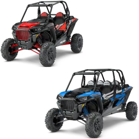
2017-2018 Index
- Polaris RZR XP Turbo and RZR XP 4 Turbo models covering 2017–2018.
- 2017 RZR XP Turbo, RZR XP 4 Turbo and RZR XP Turbo Tractor (International) variants.
- 2018 RZR XP Turbo, RZR XP 4 Turbo, FOX Edition and DYNAMIX Edition configurations, where specified.
- Service repair manual covering engine overhaul, turbocharging, electronic fuel injection, PVT drive system, transmission, AWD drivetrain, suspension, brakes, electrical diagnostics and wiring diagrams.
General Information, Maintenance & Technical Specifications
- Vehicle identification numbers (VIN), engine serial number locations, model designations and replacement key information.
- Model-specific specifications and clutch calibration charts for 2017–2018 XP Turbo, XP4 Turbo, FOX Edition and DYNAMIX Edition variants.
- Periodic maintenance schedules, pre-ride inspections, lubrication points, service products and maintenance reference information.
- Technical specifications, tightening torques, measuring procedures, special service tools and workshop reference charts.
Engine Mechanical Service & Overhaul
- Engine removal and installation, engine mounting components, crankcase assemblies and internal mechanical components.
- Cylinder head, camshafts, valves, valve seats, combustion chambers, camshaft timing and valve clearance adjustment.
- Crankshaft, connecting rods, balance shaft, pistons, piston rings, cylinders and engine bearings.
- Piston-to-cylinder clearance, piston ring gaps, crankshaft and connecting rod bearing selection, and mechanical wear inspections.
- Engine top-end and bottom-end disassembly, inspection and assembly, including flywheel, stator cover and starter one-way clutch.
- Cylinder head assembly, valve sealing tests, camshaft installation, timing procedures and tappet selection.
Turbocharger, Intake & Exhaust Systems
- Turbocharger operation, removal, installation, inspection and servicing.
- Turbocharger actuator, wastegate, actuator pod, oil drain tube and wastegate flapper inspection.
- Air intake assembly, airbox removal and installation, intake pre-filter servicing and intake duct inspection.
- Exhaust manifold, head pipe, turbocharger assembly, exhaust pipes and muffler removal and installation.
- Turbocharger troubleshooting, exhaust heat shield inspection and spark arrestor maintenance.
Cooling System & Charge Air Cooling
- Engine cooling system operation, coolant flow, technical specifications and pressure testing.
- Radiator removal, installation, inspection and cleaning, coolant hoses, thermostat replacement and water pump servicing.
- Charge air cooler removal and installation.
- Engine cooling and charge air cooling system bleeding procedures.
- Coolant strength inspection, coolant flushing, electric coolant pump servicing and cooling system troubleshooting.
Electronic Fuel Injection (EFI) & Fuel System
- EFI system operation, component locations, initial fuel priming and starting procedures.
- Electronic Control Unit (ECU) servicing, replacement and electronic throttle learning procedures.
- Fuel injector testing, troubleshooting, replacement and injector O-ring servicing.
- Fuel tank removal and installation for XP and XP4 models, fuel pump replacement, fuel pressure testing and fuel level sender inspection.
- Fuel line removal and installation, fuel tank ventilation and vent line routing.
- Barometric Air Pressure (BAP), boost pressure and TMAP sensors, including intake air temperature sensor information.
- Fuel system diagnostics, cylinder misfire detection and Digital Wrench data troubleshooting.
Engine Electronic Management & Sensors
- Electronic Throttle Control (ETC), throttle body inspection, testing, replacement and throttle learning procedures.
- Crankshaft Position Sensor (CPS), Pedal Position Sensor (PPS), knock sensor and oxygen sensor testing and replacement.
- ECU operation, replacement, reprogramming and diagnostic procedures.
- Electronic engine management troubleshooting and sensor-related service information.
Polaris Digital Wrench Diagnostics
- Polaris Digital Wrench® diagnostic software operation, special tools and diagnostic connector information.
- Guided diagnostics, communication error troubleshooting, software versions and updates.
- ECU replacement, Electronic Throttle Control learning and ECU reprogramming (reflash).
- Polaris Mobile Digital Wrench (PMDW) reference information.
- Diagnostic data analysis and electronic fuel injection troubleshooting.
PVT Clutch & Drive Belt System
- Polaris Variable Transmission (PVT) system operation, drive clutch and driven clutch components.
- Drive belt removal, inspection, installation and break-in procedures.
- Drive clutch removal, disassembly, inspection, assembly and installation.
- Shift weight inspection, slider plate inspection and clutch component servicing.
- Driven clutch removal, disassembly, inspection, assembly and installation.
- Model-specific clutch calibration charts for 2017–2018 XP Turbo and XP4 Turbo variants.
- PVT troubleshooting, intake pre-filter maintenance and system drainage.
Transmission & Gear Selection
- Transmission removal, installation, disassembly and assembly.
- Transmission gear clusters, shafts, bearings and internal gear components.
- Snorkel tube removal and disassembly, snorkel gear backlash inspection and adjustment.
- Shift lever removal and installation, shift cable inspection and adjustment.
- Transmission oil level inspection, lubrication, oil replacement and vent line routing.
- Troubleshooting procedures for shifting difficulties.
AWD, Front Gearcase & Final Drive
- All-Wheel Drive (AWD) operation and diagnosis, including the Centralized Hilliard front gearcase.
- Front gearcase removal, disassembly, inspection, assembly and installation.
- Front and rear drive shaft removal and installation, CV joint servicing and inner/outer CV boot replacement.
- Propeller shaft removal and installation for XP and XP4 models, universal joint servicing and support bearing replacement.
- Front and rear bearing carrier inspection, removal and installation, including wheel bearing replacement.
- Front gearcase lubrication, fluid inspection, oil replacement and vent line routing.
Steering & Electronic Power Steering (EPS)
- Steering system inspection, steering wheel free play and wheel toe alignment inspection and adjustment.
- Steering wheel, upper and lower steering shafts, steering shaft bushings and power steering unit removal and installation.
- Electronic Power Steering (EPS) operation, system diagnosis and troubleshooting.
- EPS fault diagnosis with and without malfunction indicator activation, including Polaris Digital Wrench® procedures.
Front & Rear Suspension
- Front suspension components, A-arms, stabilizer bars and ball joint removal, inspection and replacement.
- Rear suspension trailing arms, spherical bearings, radius rods and stabilizer bars.
- Shock absorber removal, installation, spring replacement, spring adjustment and compression damping adjustment.
- FOX 2.5-inch front and FOX 3.0-inch rear shock absorber service information.
- FOX Podium Bypass shock absorber disassembly and assembly procedures.
- Walker Evans 2.0-inch front and 2.5-inch rear shock absorber servicing, spring adjustment, piston orientation and valve shim arrangements.
DYNAMIX Active Suspension (2018 Models, If Equipped)
- DYNAMIX active suspension system operation, electronically controlled shock absorbers and suspension control features.
- Suspension Control Module (SCM) operation and replacement, suspension mode switch and inertial measurement unit.
- Vehicle speed sensitivity, cornering control, braking, acceleration and airborne detection functions.
- DYNAMIX shock absorber disassembly and assembly procedures.
- SCM voltage checks, shock valve diagnostics, CAN communication testing and steering angle offset diagnostics.
- DYNAMIX troubleshooting, advanced diagnostics and system inspection procedures.
Hydraulic Braking System
- Brake system specifications, hydraulic brake operation, brake line routing and component servicing.
- Brake master cylinder and brake pedal removal and installation, brake fluid replacement and hydraulic system bleeding.
- Front and rear brake caliper removal, disassembly, inspection and assembly.
- Brake pad inspection and replacement, brake disc inspection and replacement, and brake burnishing procedures.
- Secondary hand brake system servicing for applicable international models.
- Troubleshooting brake noise, poor braking performance, pedal vibration, overheating, dragging brakes and brake locking conditions.
Body, Chassis & Exterior Components
- Cab frame, chassis and main frame assembly information for XP and XP4 configurations.
- Front and rear bumpers, hood, fenders, front bodywork, cargo box, floor panels, rocker panels and console.
- Seat assemblies, engine service panels, dashboard and operating controls.
- Body panel removal, chassis assembly views and exterior component servicing.
- Bodywork disassembly procedures and decal replacement information.
Electrical Equipment, Battery & Charging System
- Battery specifications, inspection, load testing, open-circuit voltage testing, charging and off-season storage.
- Charging system testing, stator resistance and AC voltage output measurements.
- Regulator/rectifier servicing for DYNAMIX and non-DYNAMIX configurations.
- Starter solenoid operation, replacement and bench testing.
- Ignition coil testing, high-tension lead replacement and spark plug maintenance.
- Headlight adjustment and replacement, taillights and dashboard lighting.
- Fuse and relay locations, fuse/relay centre configurations and voltage regulator fusible links.
Instrument Cluster, Switches & Controls
- Instrument cluster operation, indicator lamps, display configuration and diagnostic code display.
- Instrument cluster connector pinouts, removal and installation.
- Display settings for distance, temperature, clock, backlight colour, brightness and service hours.
- Headlight switch, ignition switch, AWD/2WD switch, seat belt switch, transmission position switch and brake pressure switch.
- Boost control solenoid, DYNAMIX suspension mode switch and steering angle sensor centering.
- International/Tractor model electrical controls, including hazard lights, turn signals, horn, flasher module, brake alarm and parking brake switch.
Electrical Diagnostics, CAN Bus & Wiring Harnesses
- Digital multimeter testing, electrical connector probing and static/dynamic electrical testing.
- Continuity and resistance measurements, short-to-ground and short-to-voltage testing.
- Intermittent fault diagnosis, current flow testing, parasitic draw measurements and voltage drop testing.
- Controller Area Network (CAN) operation and communication system testing.
- Main wiring harness routing, retention points, harness replacement and break-out diagram information.
- Electrical component locations, engine/chassis grounding points and electrical service procedures.
- Diagnostic Trouble Code (DTC) reference list and instrument cluster diagnostic information.
Electrical Wiring Diagrams (EWD)
- Dedicated electrical wiring diagrams for 2017 and 2018 Polaris RZR XP Turbo and RZR XP 4 Turbo configurations.
- 2017 RZR Turbo wiring diagrams.
- 2017 RZR 4 Turbo wiring diagrams.
- 2018 RZR Turbo wiring diagrams.
- 2018 RZR XP Turbo Crew wiring diagrams.
- 2018 RZR XP Turbo DYNAMIX wiring diagrams.
- 2017–2018 RZR Turbo Tractor (International) wiring diagrams.
Troubleshooting & Diagnostic Reference
- Engine mechanical, cooling system and turbocharger troubleshooting.
- Electronic fuel injection diagnostics, fuel injector testing and cylinder misfire detection.
- PVT drive system, transmission shifting and AWD troubleshooting.
- Electronic power steering, DYNAMIX suspension and CAN communication diagnostics.
- Hydraulic braking system troubleshooting and electrical fault testing.
- Diagnostic Trouble Codes (DTC), Polaris Digital Wrench® procedures and ECU diagnostic functions.
Technical Reference Data & Special Tools
- Engine lubrication specifications, mechanical service limits, engine tightening torques and camshaft timing reference information.
- Vehicle specifications, clutch calibration charts, suspension settings and brake system specifications.
- Special service tools for engine, transmission, PVT, final drive, suspension, brakes and electrical diagnostics.
- Workshop reference tables, SAE and metric tap/drill sizes, decimal equivalents and measurement conversions.
Practical Diagnostic Use Cases: The DYNAMIX Network
In many real-world repair cases, guys drag their RZR into the bay with a ridiculously stiff ride and a glowing MIL, assuming a Fox shock valve is physically jammed. On the Dynamix Edition models, the suspension isn't just hydraulic; it's a heavily networked electronic system.
The Suspension Control Module (SCM) relies heavily on vehicle speed, braking inputs, and steering angle data transmitted over the CAN network. ECU misinterpretation due to faulty mechanical components is incredibly common here. For example, if a heavy trail impact bends a tie rod, the steering wheel sits off-center. The steering angle sensor reads this mechanical misalignment and the SCM automatically disables the active valving, locking the shocks into full-firm for safety. This resource maps out the complete SCM wiring circuits and adapted offset diagnostics so you can separate actual electrical failures from simple suspension geometry tweaks.
Drivetrain Engineering Breakdown
When dealing with a 168-horsepower turbo engine, the Polaris Variable Transmission (PVT) takes a brutal beating. One frequent diagnostic mistake is completely isolating mechanical driveline damage from engine electronic faults when pulling OBD2 sensor diagnostics.
When a drive belt violently fragments at wide-open throttle, the high-velocity debris and sudden massive vibration frequently slap against the engine block. A common issue technicians encounter is tracing an intermittent cylinder misfire code or rough idle, only to discover that the exploding belt physically damaged the Crankshaft Position Sensor (CPS) wiring or the knock sensor harness routed directly behind the inner clutch cover. This technical document provides the complete engine teardown guide to address the mechanical carnage, alongside the exact connector pinouts needed to verify sensor integrity. It also highlights the precise tightening sequences required when reinstalling the drive and driven clutches to prevent a repeat failure.
Electrical Distribution & Trail Diagnostics
Tracking down a dead pedal response on the Electronic Throttle Control (ETC) system without accurate diagrams is a nightmare. Before replacing an expensive throttle body, practical diagnostics dictate testing the Pedal Position Sensor (PPS) 5-volt reference circuit.
Overlooking grounding issues affecting system performance is a massive trap on UTVs. Because these machines live in mud, water, and sand, chassis grounds corrode rapidly. A degraded ground on the main harness can trigger a cascade of false EFI codes and fuel pump pressure drops, severely complicating your RZR parasitic draw diagnosis. The detailed factory wiring schematics inside this manual reveal the exact physical locations of all engine earth points, fuse box layouts, and relay centers. For shops utilizing the Polaris Digital Wrench or PMDW software, the guide provides the necessary guided diagnostic flows to interpret complex sensor data accurately.
Heavy-Duty Powertrain Servicing
Beyond the electronics, you get exhaustive OEM service instructions for purely mechanical assemblies. Whether you are splitting the cases for a bottom-end rebuild, servicing the Centralized Hilliard front gearcase, or inspecting drivetrain components like the prop shafts and wheel hubs, the correct data is critical. Using the exact mechanical clearance tolerances and torque specifications ensures your heavy-duty overhauls handle the abuse of the trail.
Instant Access For The Shop Floor
Waiting on a printed book while a broken RZR ties up your lift isn't an option. We deliver the complete, searchable PDF straight to your email inbox instantly.
- Checkout Options: We proudly accept Credit Card, PayPal, Google Pay, and Apple Pay.
- Instant Delivery: The file drops into your inbox and is simultaneously added to your secure customer account for permanent access.
- Download Terms: Your secure link stays hot for 10 days or up to 10 full downloads, so you can load it on the shop laptop and your mobile device.
- The Backup Guarantee: Shop Wi-Fi acting up? If your download drops, shoot us an email and we will manually send you a direct Dropbox backup link.
- Need Help Downloading?: Check out this quick video tutorial on saving the PDF directly to your phone or tablet: https://servicemanuals.info/How-to-Download.mp4. Get immediate access to the full service manual and start diagnosing with precision.
Workshop Relevance & FAQs
How does this technical document handle testing AWD engagement on the front Hilliard gearcase?
It breaks down both the electrical and mechanical sides seamlessly. If the front wheels won't pull, the guide shows you how to verify the 12-volt coil signal at the armature plate. If the electronics check out, it details the physical teardown process to inspect the roll cage and H-springs for metal fatigue.
Is the Tractor (International) variant wiring drastically different from the domestic RZR?
Yes, significantly. The International models feature secondary hand brake systems, distinct hazard/turn signal switches, and unique flasher modules. The manual contains dedicated wiring sheets specifically for the Tractor variants so you aren't wasting time tracing dead-end domestic circuits.
What's the process for recalibrating the throttle pedal if I install a new ETC unit?
The Electronic Throttle Control operates on a strict voltage sweep. The guide includes the precise ETC Learn Procedure required to sync the new throttle body with the ECU, ensuring idle stability and preventing immediate limp-mode activation on startup.