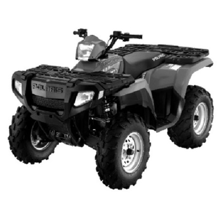
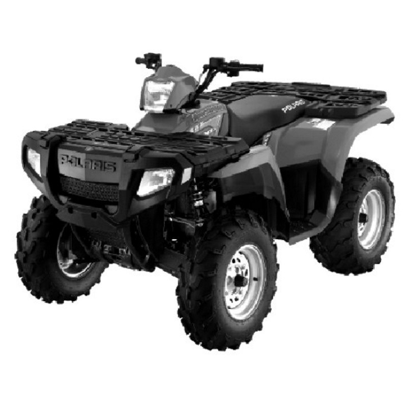
Polaris Sportsman 400 500 (2005) - Service Manual - Wiring Diagram - Parts Catalogue
Digital technical documentation with sections on SERVICE MANUAL 400-500, CHAPTER 1-GENERAL, Model Identification. Review the complete contents below for the systems and procedures covered.
Manual contents
- SERVICE MANUAL 400-500
- INTRODUCTION
- TABLE OF CONTENTS
- CHAPTER 1-GENERAL
- - Model Identification
- - Serial Number Location
- - Publication Numbers
- - Paint Codes
- - Replacement Keys
- - General Specifactions -Sportsman 400/500
- - Special Tools
- - Standard Torque Specifications
- - Decimal Equivalent Chart
- - Coversion Table
- - Glossary Of Terms
- CHAPTER 2-MAINTENANCE
- - Periodic Maintenance Chart
- - Lubricant And Maintenance Product Numbers
- - Atv Component Locations
- - Lubrication Charts
- - Front Gearcase Lubrication
- - Transmission Lubrication
- - Lubrications Points
- - Transmission Linkage Ajustments
- - Carburetor/Throttle Adjustments
- - Fuel System
- - Compression Test
- - Battery Maintenance
- - Coolant System Maintenance
- - Air Filter Service
- - Air Box Sediment Tube Service
- - Breather Filter
- - Recoil Housing
- - Oil Change/Filter
- - Valve Clearance
- - Steering And Toe Alignment
- - Exhaust System Maintenance
- - Brake System Service
- - Suspension Service
- - Controls
- - Wheel Removal/Instalation
- - Tire Inspection
- - Compartment Storage
- - Warn™ Winch Operation
- - Cleaning And Storage Of Atv
- CHAPTER 3-ENGINE
- - Torue Specifications
- - Special Tools
- - Eh50pl Service Data
- - Torque Patterns
- - Piston Identification
- - Cooling System Pressure Test
- - Cooling System Specifications
- - Engine Removal
- - Engine Installation Notes
- - Cylinder Honeing
- - Crankshaft Runout Inspection
- - Eh50pl Engine Lubrication
- - Eh50pl Oil Pump Priming Procedure
- - Eh50pl Lubrication/Oil Flow
- - Eh50pl Engine Exploded View
- - Eh50pl Engine Top End Disassembly
- - Eh50pl Valve Seat Service
- - Eh50pl Cylinder Head Assembly
- - Eh50pl Engine Bottom End Disassembly
- - Eh50pl Crankcase & Bearing Assembly
- - Eh50pl Crankshaft End Play Inspection
- - Eh50pl Counter Balancer Shaft End Play Inspection
- - Eh50pl Oil Pump Shaft End Play Inspection
- - Eh50pl Engine Assembly/Inspection
- - Sealed Recoil Disassembly/Inspection
- - Sealed Recoil Assembly
- - Spark Plug Fouling Checklist
- - Troubleshooting
- CHAPTER 4-FUEL/CARBURETION
- - Exploded View, Mikuni Bst 34/40 Carburetor
- - Fuel Tank Asm. Exploded Veiw
- - Fuel Flow Diagram
- - Fuel Component Overview
- - Fuel Sender Removal/Install
- - Special Tool & Jetting Guidelines
- - Carburetor Jetting
- - Main Jet/Pilot Jet Part Numbers
- - Cv Carburetor System Function (4 Cycle)
- - Cv Carburetor Vent System (4 Cycle)
- - Cv Carburetor Operation
- - Pilot Screw Information
- - Disassembly Notes, Cv Carburetor
- - Cleaning, Cv Carburetor
- - Inspection, Cv Carburetor
- - Assembly, Cv Carburetor
- - Float Adjustment, Cv Carburetor
- - Needle & Seat Leakage Test
- - Fuel Level
- - Fuel Pump Service
- - Troubleshooting
- CHAPTER 5-BODY AND STEERING
- - Torque Specifications And Special Tools
- - Plastic Insert Removal/Install
- - Side Panel Removal
- - Front Cover Removal
- - Foot Well Removal/Install
- - Front Storage Removal/Install
- - Rear Rack Remove/Install
- - Front Cab / Fender Remove/Install
- - Rear Cab / Fender Remove/Install
- - Radiator Screen Removal
- - Body Assembly, Exploded View
- - Headlight Pod, Exploded View
- - Handlebar Block Installation
- - Steering Assembly, Exploded View
- - A-Arm Replacement
- - Rear Suspension Assembly
- - Strut Assembly Exploded View
- - Front Strut Cartridge Replacement
- - Front Strut Ball Joint Replacement
- - Steering Post Assembly
- - Decal Replacement
- CHAPTER 6-CLUTCHING
- - Special Tools, Supplies & Torques
- - Pvt System Operation
- - Pvt Maintenance/Inspection
- - Pvt Disassembly
- - Pvt Assembly
- - Pvt Sealing And Ducting Components
- - Drive Clutch Exploded View
- - Drive Clutch Spring Specifications
- - Shift Weights
- - Drive Clutch Inspection
- - Drive Clutch Disassembly
- - Drive Clutch Assembly
- - Drive Belt Tension
- - Drive Belt Removal/Inspection
- - Drive Belt Installation
- - Clutch Alignment/Offset
- - Drive Clutch Bushing Service
- - Driven Clutch Disassembly/Inspection
- - Driven Clutch Assembly
- - Driven Clutch Bushing Service
- - Ebs Exploded View
- - Ebs Drive Clutch Disassembly/Inspection
- - Ebs Drive Clutch Bushing Service
- - Ebs Driven Clutch Disass./Insp.
- - Ebs Driven Clutch Bushing Serv.
- - Troubleshooting
- CHAPTER 7-FINAL DRIVE
- - Final Drive Torque Specifications
- - Awd Front Axle Remove/Install
- - Awd Front Cv Joint Boot Replace
- - Awd Front Drive Axle Exploded View
- - Front Hub Disass./Assemble
- - Awd Front Prop Shaft Removal
- - U-Joint Disassemble/Assemble
- - Drive Axle / Propshaft Exploded View
- - Awd Front Gearcase Operation
- - Awd Front Gearcase Service
- - Rear Hub Remove/Install
- - Rear Hub Disassembly/Assembly
- - Rear Drive Shaft Removal
- - Driveshaft / Cv Joint Tips
- - Rear Driveshaft Installation
- - Rear Driveshaft Service
- CHAPTER 8-TRANSMISSION
- - Transmission Mounting
- - Torque Specifications
- - Special Tools
- - Transmission Removal
- - Transmission Installation
- - Transmission Disassembly
- - Transmission Assembly
- - Troubleshooting
- - Transmission Exploded View
- CHAPTER 9-BRAKES
- - Special Tools/Specifications/Torques
- - Brake System Components
- - Rear Caliper Exploded View
- - Front Caliper Exploded View
- - Rear Auxiliary Master Cylinder Exploded View
- - Brake System Service Notes
- - Brake Noise Troubleshooting
- - Hydraulic Brake System Overview
- - Hydraulic Caliper Bleeding
- - Brake Bleeding / Fluid Change
- - Master Cylinder Removal
- - Master Cylinder Installation
- - Front Pad Removal
- - Front Pad Assembly
- - Brake Burnishing
- - Front Disc Inspection
- - Front Disc Removal/Replacement
- - Front Caliper Removal
- - Front Caliper Disassembly
- - Front Caliper Inspection
- - Front Caliper Reassembly
- - Front Caliper Installation
- - Rear Pad Removal
- - Rear Pad Installation
- - Rear Caliper Removal/Inspection
- - Rear Caliper Reassembly
- - Rear Disc Inspection
- - Rear (Auxiliary) Brake Remove/Install
- - Troubleshooting
- CHAPTER 10-ELECTRICAL
- - Special Tools/Service Notes
- - Gear Position Switch Test
- - Ecm Operation
- - Electrical Components
- - Instrument Cluster Operation
- - Speedometer Removal/Installation
- - Speedometer Troubleshooting
- - Coolant Sensor Tests
- - Fan Motor Tests
- - Electronic Throttle Circuit System Operation
- - Ignition System Information
- - Ignition System Testing Flow Chart
- - Ignition System Troubleshooting
- - Cdi Output Tests
- - Charging System Testing
- - Timing Check Procedure
- - Battery Activation/Service
- - Head Light/Brake Light Lamp Service
- - Fuel Sender Test
- - Accessory Wire Hookup
- - Warn™ Winch Wiring Schematic
- - Starter System Troubleshooting
- - Starter Motor Service
- - Starter Drive
- - Starter Assembly Exploded View
- - Starter System Testing Flow Chart
- WIRING DIAGRAMS
- INDEX
- - A-C
- - C-E
- - E-G
- - G-P
- - P-T
- - T-W
- PARTS MANUAL 400
- PARTS MANUAL 500