• -$10.00
Moto Guzzi California 1400 Workshop, Wiring & Parts Manuals
search
  • Moto Guzzi California 1400 Workshop, Wiring & Parts Manuals

Moto Guzzi California 1400 Workshop, Wiring & Parts Manuals

$29.95
$19.95 Save $10.00
No tax
Quantity

YOUTUBE Official Channel @SoloPDFcom (+18,000 subs). Trusted by mechanics worldwide using professional workshop manuals and wiring diagrams.

Moto Guzzi California 1400 Workshop, Wiring & Parts Manuals

A technical collection containing workshop or maintenance chapters and separately indexed electrical diagrams or circuit documentation. Each source section retains its original scope.

Technical areas in the source: engine and powertrain, transmissions and driveline, brakes and steering, suspension and axles, electrical circuits and components.

Examples from the original contents: MANUALS INCLUDED:; Maintenance rules; Checking the desmodromic drum; ERRORS screen page.

Languages identified in the original listing: Multiple language editions are individually identified. Individual documents may use different languages.

Document scope: Service, electrical and parts material separated by California 1400 editions and document titles in the source index.

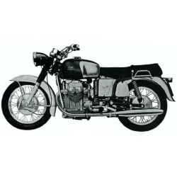
Original technical index

  • MANUALS INCLUDED:
  • - CALIFORNIA 1400 2012 SERVICE MANUAL (ENGLISH)
  • - CALIFORNIA 1400 2012 MANUALE DI SERVIZIO (ITALIANO)
  • - CALIFORNIA 1400 2012 MANUEL DE REPARATION (FRANCAIS)
  • - CALIFORNIA 1400 2012 MANUAL DE TALLER (ESPAÑOL)
  • - CALIFORNIA 1400 2012 WERKSTATTHANDBUCH (DEUTSCH)
  • - CALIFORNIA 1400 2012 OWNERS MANUAL (ENGLISH)
  • - CALIFORNIA 1400 2012 MANUALE DEL PROPRIETARIO (ITALIANO)
  • - CALIFORNIA 1400 2012 MANUEL D'UTILISATEUR (FRANCAIS)
  • - CALIFORNIA 1400 2012 MANUAL DE USO (ESPAÑOL)
  • - CALIFORNIA 1400 2012 BEDIENUNGSANLEITUNG (DEUTSCH)
  • - CALIFORNIA 1400 2013 CUSTOM ABS PARTS CATALOGUE (ENGLISH)
  • - CALIFORNIA 1400 2013 CUSTOM ABS CATALOGUE DE PIECES DE RECHANGE (FRANCAIS)
  • - CALIFORNIA 1400 2013 CUSTOM ABS ERSATZTEILKATALOG (DEUTSCH)
  • - CALIFORNIA 1400 2013 TOURING ABS PARTS CATALOGUE (ENGLISH)
  • - CALIFORNIA 1400 2013 TOURING ABS CATALOGUE DE PIECES DE RECHANGE (FRANCAIS)
  • - CALIFORNIA 1400 2013 TOURING ABS ERSATZTEILKATALOG (DEUTSCH)
  • - CALIFORNIA 1400 2013 OWNERS MANUAL (ENGLISH - ESPAÑOL)
  • - CALIFORNIA 1400 2013 OWNERS MANUAL (ITALIANO-FRANCAIS)
  • - CALIFORNIA 1400 2013 OWNERS MANUAL (FRANCAIS-ENGLISH)
  • - CALIFORNIA 1400 2013 OWNERS MANUAL (ESPAÑOL-ITALIANO
  • - CALIFORNIA 1400 2013 OWNERS MANUAL (DEUTSCH)
  • - CALIFORNIA 1400 2014 CLASSIC TOURING SERVICE MANUAL (ENGLISH)
  • - CALIFORNIA 1400 2014 CLASSIC TOURING MANUALE DI SERVIZIO (ITALIANO)
  • - CALIFORNIA 1400 2014 CLASSIC TOURING MANUEL DE REPARATION (FRANCAIS)
  • - CALIFORNIA 1400 2014 CLASSIC TOURING MANUAL DE TALLER (ESPAÑOL)
  • - CALIFORNIA 1400 2014 CLASSIC TOURING WERKSTATTHANDBUCH (DEUTSCH)
  • - CALIFORNIA 1400 2012 ESQUEMA ELECTRICO (HASTA M200035)
  • - CALIFORNIA 1400 2012 ESQUEMA ELECTRICO
  • - CALIFORNIA 1400 2012 SCHALTPLAN (BIS M200035)
  • - CALIFORNIA 1400 2012 SCHALTPLAN
  • - CALIFORNIA 1400 2012 SCHEMA ELECTRIQUE (JUSQUA M200035)
  • - CALIFORNIA 1400 2012 SCHEMA ELECTRIQUE
  • - CALIFORNIA 1400 2012 SCHEMA ELETTRICO (FINO M200035)
  • - CALIFORNIA 1400 2012 SCHEMA ELETTRICO
  • - CALIFORNIA 1400 2012 WIRING DIAGRAM (UNTILM200035)
  • - CALIFORNIA 1400 2012 WIRING DIAGRAM
  • - CALIFORNIA 1400 2014 ESQUEMA ELECTRICO (DEL M200036)
  • - CALIFORNIA 1400 2014 SCHALTPLAN (AB M200036)
  • - CALIFORNIA 1400 2014 SCHEMA ELETTRICO (DAL M200036)
  • - CALIFORNIA 1400 2014 WIRING DIAGRAM (ENTIRE 2014)
  • - CALIFORNIA 1400 2014 WIRING DIAGRAM (FROM M200036 ENTIRE)
  • - CALIFORNIA 1400 2014 WIRING DIAGRAM (FROM M200036 ENTIRE)
  • - CALIFORNIA 1400 2014 WIRING DIAGRAM (FROM M200036 LEGEND)
  • - CALIFORNIA 1400 2014 WIRING DIAGRAM (FROM M200036 LEGEND)
  • - CALIFORNIA 1400 2014 WIRING DIAGRAM (FROM M200036)
  • - CALIFORNIA 1400 2014 WIRING DIAGRAM ENABLING SIGNAL I
  • - CALIFORNIA 1400 2014 WIRING DIAGRAM ENABLING SIGNAL II
  • - CALIFORNIA 1400 2014 WIRING DIAGRAM GROUND
  • - CALIFORNIA 1400 2014 WIRING DIAGRAM LEGEND
  • - CALIFORNIA 1400 2014 WIRING DIAGRAM POWER SUPPLY
  • SAMPLE INDEX SERVICE MANUAL:
  • ENGLISH
  • Characteristics
  • - Rules
  • - Safety rules
  • - Maintenance rules
  • - Running-in
  • - Vehicle identification
  • - Dimensions and mass
  • - Engine
  • - Transmission
  • - Capacities
  • - Electrical system
  • - Frame and suspensions
  • - Brakes
  • - Wheels and tyres
  • - Tightening Torques
  • - Chassis
  • - Front side
  • - Central part
  • - Back side
  • - Engine
  • - Overhaul data
  • - Assembly clearances
  • - Cylinder - piston assy.
  • - Piston rings
  • - Slot packing system
  • - Recommended products chart
  • Special tools
  • Maintenance
  • - Maintenance chart
  • - Transmission fluid
  • - Check
  • - Replacement
  • - Engine oil
  • - Check
  • - Replacement
  • - Engine oil filter
  • - Gearbox Oil
  • - Inspection
  • - Replacement
  • - Air filter
  • - Checking the valve clearance
  • - Braking system
  • - Level check
  • - Top-up
  • Electrical system
  • - Components arrangement
  • - Electrical system installation
  • - Front side
  • - Central part
  • - Back side
  • - General wiring diagram
  • - Checks and inspections
  • - Immobiliser
  • - Dashboard
  • - Diagnosis
  • - Start-up system check
  • - Fuses
  • - Control unit
  • - Battery
  • - Speed sensor
  • - Engine rpm sensor
  • - Twistgrip position sensor
  • - Intake pressure sensor
  • - Engine temperature sensor
  • - Lambda sensor
  • - Injector
  • - Fuel pump
  • - Coil
  • - Throttle body
  • - Engine oil pressure sensor
  • - Neutral sensor
  • - Clutch lever sensor
  • - Side stand sensor
  • - Bank angle sensor
  • - RUN/STOP switch
  • - Connectors
  • - ECU
  • - Dashboard
  • - ABS Modulator
  • - Can line
  • Engine from vehicle
  • - Vehicle preparation
  • - Removing the engine from the vehicle
  • - Installing the engine-the vehicle
  • Engine
  • - Gearbox
  • - Diagram
  • - Gearbox
  • - Removing the gearbox
  • - Installing the gearbox
  • - Gearbox shafts
  • - Disassembling the gearbox
  • - Removing the primary shaft
  • - Removing the secondary shaft
  • - Checking the primary shaft
  • - Checking the secondary shaft
  • - Checking the desmodromic drum
  • - Checking the forks
  • - Fitting the primary shaft
  • - Fitting the secondary shaft
  • - Assembling the gearbox
  • - Generator
  • - Tensioning the belt
  • - Removing the generator
  • - Installing the generator
  • - Starter motor
  • - Removing the starter motor
  • - Clutch side
  • - Disassembling the clutch
  • - Checking the clutch actuator
  • - Assembling the clutch
  • - Heads
  • - Head and timing
  • - Removing the head cover
  • - Removing the cylinder head
  • - Cylinder head
  • - Removing the overhead camshaft
  • - Removing the rocker arms
  • - Removing the valves
  • - Checking the valve guides
  • - Checking the cylinder head
  • - Installing the valves
  • - Installing the rocker arms
  • - Installing the overhead camshaft
  • - Timing
  • - Removing the phonic wheel
  • - Service shaft removal
  • - Installing the service shaft
  • - Installing sliders
  • - Cam timing
  • - Measuring air gap
  • - Cylinder-piston assembly
  • - Removing the cylinder
  • - Disassembling the piston
  • - Fitting the piston
  • - Installing the cylinder
  • - Installing the cylinder head
  • - Installing the head cover
  • - Crankcase - crankshaft
  • - Removing the crankshaft
  • - Disassembling the connecting rod
  • - Inspecting the crankshaft components
  • - Checking the connecting rod
  • - Assembling the connecting rod
  • - Installing the crankshaft
  • - Refitting the crankcase halves
  • - Lubrication
  • - Conceptual diagrams
  • - General characteristics
  • - Oil pump
  • - Removing
  • - Installing
  • - Removing the oil sump
  • - Refitting the oil sump
  • - Blow-by
  • Power supply
  • - Circuit diagram
  • - Injection
  • - Diagram
  • - ECU INFO screen page
  • - PARAMETERS screen page
  • - ACTIVATION screen page
  • - STATUS screen page
  • - ERRORS screen page
  • - SETTINGS screen page
  • Suspensions
  • - Front
  • - Removing the front wheel
  • - Checking the front wheel
  • - Handlebar
  • - Removing
  • - Front fork
  • - Removing the fork legs
  • - Draining oil
  • - Disassembling the fork
  • - Checking the components
  • - Reassembling the fork
  • - Filling oil
  • - Installing the fork legs
  • - Removing
  • - Steering bearing
  • - Adjusting play
  • - Disassembling
  • - Assembling
  • - Rear
  • - Removing the rear wheel
  • - Checking the rear wheel
  • - Installing the rear wheel
  • - Shock absorbers
  • - Removing
  • - Installing
  • Chassis
  • - Swinging arm
  • - Removing
  • - Cardan shaft
  • - Removing
  • - Checking
  • - Stand
  • - Side stand
  • - Exhaust
  • - Removing the manifold - tail pipe
  • - Engine oil cooler
  • Braking system
  • - Interventions rules
  • - ABS
  • - Foreword
  • - Operating diagram
  • - Guide-diagnosis
  • - ECU INFO screen page
  • - PARAMETERS screen page
  • - ACTIVATION screen page
  • - ERRORS screen page
  • - SETTINGS screen page
  • - Modulator
  • - Component maintenance
  • - Disc Inspection
  • - Disc Inspection
  • - Front brake pads
  • - Removal
  • - Installing
  • - Rear brake pads
  • - Removal
  • - Installing
  • - Bleeding the braking system
  • - Front
  • - Rear
  • Bodywork
  • - Engine guard
  • - Side fairings
  • - Rear rack
  • - Instrument panel
  • - Headlight assy.
  • - Additional lights
  • - Footrest
  • - Side body panels
  • - License plate holder
  • - Rear mudguard
  • - Fuel tank
  • - Rear wheelhouse
  • - Front mudguard
  • - Side panniers
  • - Pannier mounting
  • - Top-case
  • - Rear
  • - Rear grab rail
  • - Windscreen
  • - Battery
  • Pre-delivery
  • - Aesthetic inspection
  • - Tightening torques inspection
  • - Electrical system
  • - Levels check
  • - Road test
  • - Static test
  • - Functional inspection
  • - Specific operations for the vehicle