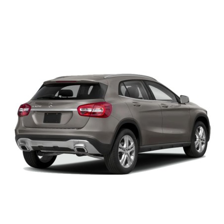
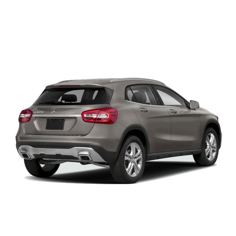
Electrical wiring diagrams for the 2017, 2018, 2019, and 2020 Mercedes-Benz GLA250.
Engine & Powertrain Systems
- Engine Performance circuits for the 2.0L Turbo and 2.0L Turbo Flex engines.
- Starting and charging system diagrams, engine accessories, and cooling fan circuits.
- Transmission and shift interlock electrical controls.
Power & Data Distribution
- Power distribution and ground distribution networks.
- Computer data lines and vehicle communication networks.
- Body Control Modules (BCM) wiring.
Chassis, Suspension & Brakes
- Anti-Lock Brakes (ABS) electrical circuits.
- Electronic Power Steering (EPS) schematics.
- Electronic Suspension system wiring.
Safety & Security Systems
- Supplemental Restraints (airbags) and vehicle warning systems.
- Anti-Theft system electrical circuits.
- Cruise control wiring.
Comfort, Convenience & Body Electrical
- Air conditioning and defogger circuits.
- Instrument cluster, horn, and wiper/washer electrical circuits.
- Wiring for power seats and integrated memory systems.
- Power windows, power mirrors, and power door locks.
- Power top and sunroof schematics.
- Trunk, tailgate, and fuel door release wiring.
Lighting Systems
- Headlights and exterior lighting circuits.
- Interior lighting schematics.
Infotainment & Navigation
- Radio and audio system wiring.
- Navigation system electrical circuits.
Engineering Breakdown
Modern automotive electronics have evolved into a sophisticated web of interconnected control modules and high-speed data streams. The Mercedes-Benz GLA250 (2017-2020) is no exception, utilizing a high-density electrical network to manage its 2.0L turbocharged engine and 7-speed DCT. When a sensor fails or a circuit opens, the resulting "limp mode" or parasitic draw requires more than just a basic code reader; it requires a deep dive into the harness routing and terminal locations provided in a professional workshop reference.
This 91 MB technical document is localized in English and serves as the definitive map for the vehicle’s nervous system. It bridges the gap between mechanical hardware and digital control, offering a granular view of how power flows from the battery to the most sensitive Body Control Modules (BCM).
Technical System Coverage
This resource is meticulously organized by model year and system type, ensuring that technicians can isolate specific circuits without sifting through irrelevant data. Within these 520 pages, you will find:
- Engine & Performance Logic: Detailed EWDs for the 2.0L Turbo and Turbo Flex variants, covering ignition coils, fuel injection pulses, and turbocharger wastegate actuators.
- Computer Data Lines: Comprehensive schematics for the CAN-bus communication network, essential for diagnosing communication U-codes between the ECU, TCM, and ABS modules.
- Power & Ground Distribution: Clear maps of fuse box layouts, splice points, and ground distribution nodes to troubleshoot total system power loss or localized voltage drops.
- Safety & Comfort Electronics: Full circuit analysis for Supplemental Restraints (Airbags), Electronic Suspension, and the Power Top/Sunroof assemblies.
- Chassis Control: Wiring for the Electronic Power Steering and Anti-Lock Brake (ABS) systems, including sensor-to-module signal paths.
Practical Diagnostic Use Cases
In practical diagnostics, having the correct Mercedes-Benz GLA250 Wiring Diagram transforms the way you approach a fault. Consider these real-world repair scenarios where this manual becomes indispensable:
- Fault Tracing for No-Start Conditions: Instead of guessing, use the Starting/Charging schematics to verify the signal from the ignition switch through the shift interlock to the starter solenoid.
- Voltage Drop Analysis: Identify high-resistance connections in the cooling fan or secondary air pump circuits by cross-referencing wire colors and terminal locations.
- Trace Open or Short Circuits: If a fuse for the power windows or exterior lights keeps blowing, the harness routing diagrams allow you to pinpoint exactly where a wire might be chafing against the chassis.
- Signal Verification: Use the connector pinouts to back-probe sensors for the 7-speed DCT, ensuring the transmission control module is receiving accurate gear position data.
Workshop Relevance: Why Accurate Data Matters
Attempting to repair a Mercedes-Benz without an accurate EWD manual PDF is a high-stakes gamble. Modern subcompact luxury SUVs use sensitive semiconductors that can be permanently damaged by incorrect probing or improper grounding. For this reason, professional technicians rely on verified schematics to prevent "cooking" an expensive ECU or Body Control Module.
Therefore, utilizing this wiring diagrams download is not just about fixing a car; it is about risk mitigation. By knowing the exact splice points and connector pinouts, you save hours of labor and eliminate the "parts cannon" approach, where components are replaced blindly in hopes of a cure. In turn, this precision leads to faster turnaround times and lower repair costs.
Technical Features
- Searchable PDF Format: Navigate the 520 pages instantly using keyword searches for specific modules or sensors.
- Ultra-Zoom Capability: High-resolution vector graphics allow you to zoom in on wire colors and codes without pixelation, which is crucial for identifying small-gauge wires in a dense harness.
- High-Detail Schematics: Every diagram includes clear legends for terminal identifiers and circuit designations.
- Multi-Device Compatibility: Carry the entire electrical library on your smartphone, tablet, or laptop for use directly at the vehicle.
Payment & Instant Delivery
Securing your technical documentation is a seamless, automated process designed for immediate workshop use:
- Payment Methods: We accept Credit Card, PayPal, Google Pay, and Apple Pay.
- Delivery: An automated download link is sent to your email immediately after purchase. The file is also stored in your customer account for easy access.
- Conditions: Your link is valid for 10 days or 10 downloads, allowing you to save the file to multiple devices.
- Guarantee: We provide a backup delivery via Dropbox if you encounter any server-side issues.
Instructional Guide: For a visual walkthrough of the process, refer to our video: Video Tutorial: How to Download.
Frequently Asked Questions
Where can I find the fuse box layout for a 2019 GLA250?
The 2019 section of this manual includes the complete "Power Distribution" and "Body Control Modules" chapters. These pages detail the exact fuse locations, amperage ratings, and the specific circuits they protect, which is the first step in any electrical diagnostic.
Does this PDF provide the pinouts for the GLA250's infotainment and navigation system?
Yes. Under the "Radio" and "Navigation" headings for each model year, you will find the full connector pinouts and harness routing for the audio system and display interface, allowing you to troubleshoot signal loss or power issues in the multimedia unit.
Will this manual show me how the CAN-bus wires are routed between the engine and transmission?
Indeed. The "Computer Data Lines" section provides a high-level overview of the data network. It shows the twisted-pair wiring paths and the gateway modules where the various CAN networks (High-speed and Low-speed) interface, which is vital for diagnosing communication faults.
Get wiring diagrams instantly and stop guessing which wire leads to the sensor.