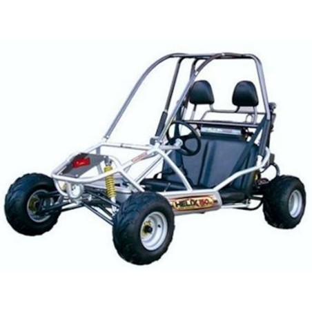
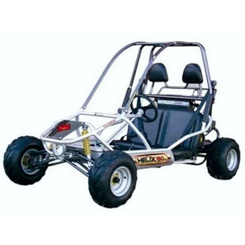
Manco 150 Fun Kart - Service Repair Manual - Wiring Diagram - Parts Catalogue
Digital technical documentation with sections on General Information and Safety, Vehicle Records, Warranty Information. Review the complete contents below for the systems and procedures covered.
Manual contents
- SERVICE MANUAL
- General Information and Safety
- Vehicle Records
- Warranty Information
- Table of Contents
- Forward
- Warnings and Cautions
- Some Words About Safety
- Are You Ready To Drive?
- Safe Driving Precautions
- Kart Operation
- Kart Operation
- Kart Features and Locations
- Kart Service
- Air Cleaner
- Engine Lubrication
- Spark Plug
- Carburetor
- General Cleaning
- General Lubrication
- Chain Lubrication and Adjustment
- Front and Rear Shock Adjustment
- Shifter Adjustment
- Storage Instruction
- General Maintenance
- Tire/Wheel Replacement
- Front End Alignment
- Speed Reduction Installation
- Replacement Parts and Service
- Specifications
- Dimensions
- Engine
- Capacities
- Miscellaneous
- Periodic Check and Service Table
- Electrical Schematic
- PARTS MANUAL
- Section 1 - Cylinder Head Assembly
- Section 2 - Cylinder
- Section 3 - Engine Crankcase
- Section 4 - Transmission
- Section 5 - CVT Cover_
- Section 6 - Outer Crankcase Assembly
- Section 7 - Piston, Crank and Connecting Rod
- Section 8 - Camshaft Assembly
- Section 9 - Oil Pump Assembly
- Section 10 - Driven Pulley and Clutch
- Section 11 - Engine Electrical
- Section 12 - Electric Start
- Section 13 - Driver Pulley
- Section 14 - Oil Cooler (Not Included on 6150 Models)
- Section 15 - Fan Cover and Shroud Assembly
- Section 16 - Carburetor
- Section 17 - Frame Group
- Section 18 - Steering Assembly
- Section 19 - Front Suspension
- Section 20 - Rear Cargo Rack
- Section 21 - Rear Swingarm
- Section 22 - Engine
- Section 23 - Rear Axle
- Section 24 - Electrical
- ENGINE PARTS MANUAL
- E-1 Fan Cover/Shroud
- E-2 Cylinder Head Cover
- E-3 Cylinder Head
- E-4 Camshaft/Valve
- E-5 Cam Chain/Tensioner
- E-6 Cylinder Comp.
- E-7 Right Crankcase Cover
- E-8 Generator
- E-9 Oil Pump
- E-10 Starter
- E-11 Left Crankcase Cover
- E-12 Drive Pulley
- E-13 Driven Pulley
- E-14 Transmission
- E-15 Crankcase
- E-16 Crankshaft/Piston
- E-17 Carburetor
- E-18 Oil Radiator
- E-19 Oil Collector
- E-20 Exhaust System
- ENGINE SERVICE MANUAL
- Chassis Nuts And Bolts
- Engine
- Lubrication System
- Fuel Supply System
- Transmission Components
- Electrical Starting System
- Belt Drive Cvt Mechanism
- Clutch
- Rear Transmission System
- Electrical System
- Ignition System
- ENGINE PARTS
- Cover Comp Cylinder Head
- Gasket Head Cover
- Connection,Tube Breather
- Plate ,Ward
- Cross Round Screwsm4×8
- Blot Flangem6×25
- Cylinder
- Pin Dowel 10×14
- Piston
- Pin Piston
- Circlip
- Ring?
- Ring?
- Wiper Ring
- Oil Ring
- Chain Adjuster
- Gasket Cam Chain Adjuster
- Blot Flange
- "0"Ring 9.5×1.5,Chain Adjuster
- Cross Recessed Round Screwsm4×8
- Blot Flange
- Blot Flange
- Steel Washer6.5×12.5×1.0
- Cylinder Head
- Pipe Comp In,Carburetor
- Clip Tube
- Guide Cam Chain
- Shaft Comp Cam
- Arm Rocker,Holder Cam
- Spr Valve Outer
- Spr Valve Inner
- Valve Inlet
- Valve Exhaust
- Retainer Valve Spr
- Seal Valve Stem
- Cotter Valve
- Washer Valve Inner
- Pin Dowel 10×14
- Bakelite Pad
- Washer,Bakelite Pad
- Plug Spark
- Bolt Flange With Casher M8
- Washer8.2×18.0×2.0
- Washer,Cylinder Head
- Bolt Stud 8*40
- Bolt Stud 8*40
- Nut M6
- Crank Case Assy L
- Crank Case Assy R
- Exceed Clutch
- Drive Shaft
- Chain Cam
- Chain Oil Pump Driven
- Gear,Double-Tooth
- Gear,Double-Tooth
- Bearing 6204
- Bearing 6203
- Bearing 6202
- Washer,Cylinder
- Oil Seal20×32×6
- Bush(Big)
- Iron Bush20×10.5×19
- Chain Adjuster Bolt, Hex In M6×21.5
- “O”Ring 15.2×1.5
- Oil Pump
- Bolt,Oil Pump Plate M6×30
- Sprocket Wheel,Oil Pump
- Blot Flange With Washer
- Plate,Oil Pump
- Nut M21×6
- Washer,22.2×31.0×2.2
- Blot Flange M6×12(Crank Case L)Bolt Special Flangem14×10
- Pin Dowel 8×14
- Blot Flange M6×50
- Chain Adjuster
- Bolt Stud 8*40
- Bolt Stud 8*40
- Cover R
- Rotor,A.C.G Fltwheel
- Stator Comp,A.C.G Fltwheel
- Guage Oil Level
- Cover,Oil Filter
- Spring,Oil Filter
- “O”Ring 29.5×3
- Oil Filter
- Blot Flangem8×28
- Blot Flangem5×12
- Pin Dowel 8×14
- Oil Seal 19.8×30×5
- Steel Bush 13.5×24.0×2.0
- Blot Flange With Washer M12
- Clamper
- Blot Flangem6×110
- Blot Flangem6×100
- Blot Flangem6×95
- Blot Flangem6×35
- Blot Flangem6×28
- Crankcase
- Cover Comp Mission
- Gear, Output Assy
- Middle Gear,?
- Middle Gear,Primary
- Gear Shifting
- Fork Assy
- Bearing6004
- Bearing6301
- Bearing6202
- Blot Flange With Washer M8
- Connection,Tube Breather
- Washer5.5×8.5×1.0
- Stud Bolt Special Flangem5×12
- Gasket Crankcase
- Washer,Cover L
- Oil Seal30×42×7
- Iron Bush 22×10.5×19
- Pin Dowel 8×14
- Gasket Mission Cover
- Blot Flange M6×70
- Blot Flange M6×65
- Blot Flange M6×50
- Big Cover L
- Cover,Big Cover L
- Plate Sub Assy Drive
- Drive Sprocket Assy.
- Drive Sprocket,Cvt Cooling
- Three Jaw Chuck
- Ball Bearing
- Gear,Plate Sub Assy Drive
- Starter Gear Assy
- Belt 743×20×32
- Fan Impeller
- Blot Flange M6×18
- Motor
- Plate,Starter Shift
- Blot Flange M6×14
- Blot Flange M6×16
- Blot Flange M6×100
- Pin Dowel 8×14
- Blot Flange With Washerm12
- Washer13.0×24×2.0
- Blot Flange M6×40
- Cover,A
- Cover,B
- Cover,Fan
- Pipe, Air
- Flooding Clip, Pipe
- Self Tapping Screwm5×16
- Blot Flange M6×20