WA380-5H Index
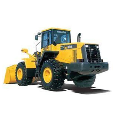
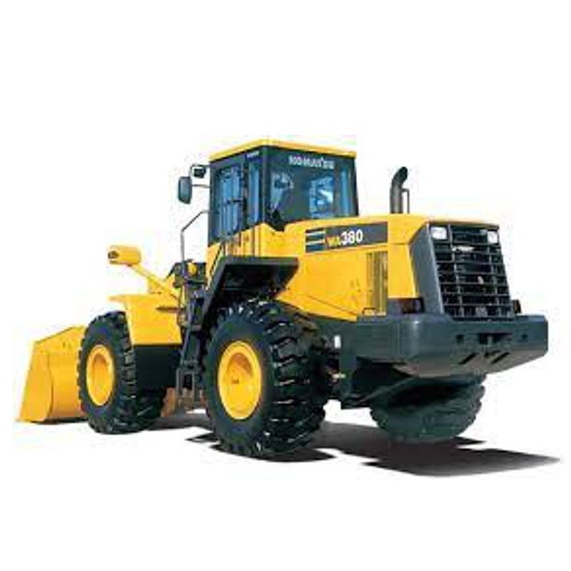
- Komatsu WA380-5H Wheel Loader.
- Service repair manual covering engine-related maintenance, power train, torque converter, transmission, axles, steering, braking, hydraulic systems, work equipment, electrical controls and machine monitoring.
- Testing and adjustment procedures, troubleshooting charts, component disassembly and assembly instructions, hydraulic circuit diagrams and electrical wiring diagrams.
- Technical specifications, maintenance standards, tightening torques, special tools and optional equipment information.
General Information, Safety & Technical Specifications
- General machine specifications, assembly drawings and component weight tables.
- Workshop safety precautions, hoisting instructions and component handling procedures.
- Standard tightening torques, coating materials, electrical wire codes and measurement conversions.
- Lubricant and coolant specifications, maintenance reference data and special service tools.
Engine Testing, Adjustment & Service
- Engine speed measurement, exhaust colour inspection and exhaust temperature measurement.
- Valve clearance adjustment and engine compression pressure testing.
- Engine blow-by pressure, engine oil pressure and intake air boost pressure measurement.
- Fuel injection timing inspection and adjustment, engine speed sensor adjustment and fuel circuit bleeding.
- Engine stop solenoid and accelerator pedal adjustment.
- Engine assembly removal and installation, engine mounting components and cylinder head servicing.
- Fuel injection pump and injection nozzle holder assembly removal and installation.
- Engine cooling system, radiator, fan motor and aftercooler assembly servicing.
Power Train & Transmission Systems
- Power train structure, operating principles and power train system diagrams.
- Engine and transmission mounting components.
- Torque converter and transmission hydraulic piping.
- Torque converter configurations with and without lock-up clutch.
- Transmission structure, transmission control valve and related hydraulic components.
- Power train oil pressure measurement, testing and adjustment.
- Torque converter and transmission hydraulic circuit flushing procedures.
- Emergency machine movement procedures when the transmission valve fails.
Torque Converter & Transmission Overhaul
- Torque converter and transmission assembly removal and installation.
- Transmission disassembly, inspection and reassembly.
- Torque converter disassembly and assembly for standard configurations without lock-up clutch.
- Torque converter disassembly and assembly for lock-up clutch configurations.
- Transmission clutch pack disassembly and assembly.
- Forward and reverse clutch pack servicing.
- First, second, third and fourth gear clutch pack servicing.
- Special tools and service procedures for transmission components.
Axles, Differentials & Final Drive
- Front and rear axle construction, operating principles and maintenance standards.
- Front and rear differential assemblies.
- Anti-slip differential operation and component information.
- Final drive assemblies and power transmission components.
- Propeller shaft and drive shaft servicing.
- Front and rear axle removal and installation.
- Axle housing disassembly and assembly.
- Differential disassembly, inspection and assembly.
- Axle mounting components and centre hinge pin removal and installation.
Hydraulic Steering System
- Steering hydraulic piping, steering column and Orbit-Roll steering components.
- Steering valve, Orbit-Roll valve and stop valve.
- Steering pump, switching pump and steering cylinders.
- Optional emergency steering pump and emergency steering motor.
- Optional joystick steering lever, steering lever and steering switch valve.
- Steering control testing and adjustment.
- Steering hydraulic oil pressure measurement.
- Steering, switching and fan pump assembly removal and installation.
- Steering demand valve and hydraulic steering cylinder servicing.
Brake System & Parking Brake
- Brake hydraulic piping, brake valve and charge valve.
- Brake accumulator operation and maintenance standards.
- Service brake components and hydraulic brake system operation.
- Parking brake control, parking brake assembly and parking brake solenoid valve.
- Parking brake emergency release valve and manual release procedures.
- Brake oil pressure testing and adjustment.
- Wheel brake disc wear inspection and parking brake disc wear inspection.
- Brake hydraulic circuit bleeding.
- Brake accumulator charging pressure inspection and adjustment.
- Parking brake disc plate removal and installation, and parking brake assembly overhaul.
Work Equipment Hydraulic System
- Hydraulic system piping, hydraulic tank and hydraulic pump assemblies.
- Torque converter charging pump, work equipment pump and pilot control pump.
- Work equipment control valve, PPC valve and PPC relief valve.
- Optional EPC solenoid valve, shut-off valve and attachment PPC valve.
- Optional travel damper valve and related hydraulic components.
- Work equipment hydraulic pressure testing and adjustment.
- Pilot control (PPC) hydraulic pressure inspection and adjustment.
- Hydraulic tank, control valve and hydraulic cylinder assembly servicing.
- Hydraulic circuit pressure release and air bleeding procedures.
Bucket, Lift Arms & Work Equipment
- Work equipment linkage, bucket assembly and hydraulic cylinders.
- Bucket positioning system and lift arm kick-out mechanism.
- Work equipment control levers and optional electronic control configurations.
- Bucket positioner testing and adjustment.
- Lift arm kick-out testing and adjustment.
- Proximity switch operation and indicator testing.
- Work equipment assembly removal and installation.
- Steering, lift and bucket hydraulic cylinder disassembly and assembly.
- Counterweight removal and installation.
Cooling System & Hydraulic Fan Drive
- Engine cooling system and related maintenance standards.
- Radiator, cooling fan motor and cooling fan motor drive pump.
- Hydraulic cooling fan testing.
- Radiator and fan motor assembly removal and installation.
- Aftercooler assembly removal and installation.
- Cooling fan and fan motor servicing.
- Cooling-related hydraulic pump and motor components.
Cab & Air Conditioning System
- Cab structure and optional cab equipment.
- Cab assembly removal and installation.
- Cab and floor frame assembly removal and installation.
- Optional air conditioning system operation and component information.
- Air conditioning unit removal and installation.
- Air conditioning compressor removal and installation.
Machine Monitor & Instrumentation
- Machine monitoring system operation and machine monitor functions.
- Speed meter specifications and optional load meter specifications.
- Machine monitor indication items, display settings and control functions.
- Machine monitor adjustment and calibration procedures.
- Optional load meter testing and adjustment.
- Machine monitor special diagnostic functions.
- Monitor-related sensor information and electrical control systems.
Electronic Transmission Control System
- Transmission electronic control system operation and system diagrams.
- Transmission controller and electric transmission control components.
- Kick-down and hold switch operation.
- Transmission speed sensor adjustment.
- Electrical connectors, transmission control circuit layouts and component locations.
- Transmission Control System troubleshooting (TM Mode).
- Transmission-related error codes and action code diagnostic procedures.
Electronic Work Equipment Control System
- Optional electronic work equipment control system.
- Work equipment controller and electrically operated work equipment control components.
- Electronic control valves, pilot control components and associated sensors.
- Work Equipment Control System troubleshooting (WRK Mode).
- Connector types, mounting locations and connector layout drawings.
- Work equipment control system diagrams, error codes and action code diagnostic procedures.
Engine Starting, Stopping & Electrical Controls
- Engine starting circuit.
- Engine stop circuit.
- Engine preheating circuit.
- Engine power mode selector circuit.
- Parking brake electrical control circuit.
- Machine sensors and related electrical control components.
- Electrical wire identification and connector reference information.
Electrical Wiring Diagrams (EWD)
- Dedicated electrical circuit diagrams included in the service manual.
- Eight-section electrical circuit diagram set, identified as Electric Circuit Diagrams 1/8 through 8/8.
- Engine starting, stopping, preheating and power mode electrical system information.
- Transmission control, work equipment control, parking brake and machine monitoring electrical system information.
- Electrical circuit references supported by connector layouts, sensor information and troubleshooting diagrams.
Electrical Connectors & Component Locations
- Electrical connector types and mounting locations.
- Connector layout drawings for transmission, work equipment, monitoring and electrical systems.
- Connector pin number connection tables.
- Electrical wire codes and connector identification information.
- System diagrams and electrical references for component location and fault diagnosis.
Transmission Control Troubleshooting (TM Mode)
- Transmission electronic control troubleshooting procedures.
- Transmission control system diagram and connector location information.
- Extensive transmission error code reference.
- TM-1 through TM-29 action code procedures, including TM-10-A and TM-10-B.
- Diagnostic procedures for transmission-related electrical and control system faults.
Work Equipment Control Troubleshooting (WRK Mode)
- Work equipment control system diagnostic procedures.
- Work equipment controller, electrical connector layouts and system diagrams.
- Work equipment control error code reference.
- WRK-1 through WRK-28 action code diagnostic procedures.
- Troubleshooting of electronically controlled hydraulic work equipment.
Machine Monitor Troubleshooting (MON Mode)
- Machine monitor system diagnostics and troubleshooting procedures.
- Monitor system diagram, electrical connectors and component locations.
- Machine monitoring error code reference.
- MON-1 through MON-20 action code diagnostic procedures.
- Monitor display, indication and associated control system troubleshooting.
Hydraulic & Mechanical Troubleshooting (H Mode)
- Hydraulic and mechanical system diagnostic procedures.
- H-1 through H-29 troubleshooting charts, including H-3A and H-3B.
- Mechanical and hydraulic fault investigation.
- Reference procedures for machine systems and work equipment malfunctions.
Electrical System Troubleshooting (E Mode)
- Electrical system diagnostic procedures and troubleshooting charts.
- Electrical component connectors, mounting locations and connector layouts.
- Electrical system diagram and related diagnostic references.
- E-1-A, E-1-B and E-2 through E-18 action code procedures.
- Electrical fault investigation and system circuit testing information.
General Testing, Adjustment & Diagnostics
- Engine and chassis standard measurement values.
- Engine performance, fuel injection, lubrication and cooling system testing.
- Transmission hydraulic pressure, steering pressure and brake pressure measurement.
- Hydraulic fan, brake accumulator and work equipment pressure testing.
- Bucket positioner, lift arm kick-out, machine monitor and load meter adjustment.
- Electrical troubleshooting equipment and diagnostic preparation.
- Fault diagnosis using error codes, action codes and system-specific troubleshooting charts.
Disassembly, Assembly & Component Repair
- Engine and cylinder head assembly removal and installation.
- Radiator, aftercooler, fuel injection pump and fuel tank servicing.
- Torque converter and transmission disassembly and assembly.
- Transmission clutch pack, parking brake and differential overhaul.
- Front and rear axle, axle housing and centre hinge pin servicing.
- Cab, floor frame, hydraulic pumps, control valves and hydraulic cylinders.
- Work equipment, counterweight and optional air conditioning component servicing.
- Special tool drawings and workshop assembly instructions.
Hydraulic & Power Train Circuit Diagrams
- Power train oil circuit diagram without torque converter lock-up clutch.
- Power train oil circuit diagram with torque converter lock-up clutch.
- Brake oil circuit diagram.
- Work equipment hydraulic circuit diagram.
- Work equipment hydraulic circuit diagram for electrically operated work equipment levers.
Technical Reference Data & Special Tools
- Machine specifications, weights and maintenance standards.
- Engine and chassis testing standards and hydraulic pressure reference values.
- Standard tightening torques and component assembly specifications.
- Lubricant, coolant and coating material information.
- Special service tools, lifting tools, brackets, spacers and press tools.
- Workshop safety instructions, electrical wire codes and measurement conversion tables.
Practical Diagnostic Use Cases
Heavy earthmoving equipment operates in brutal conditions where mechanical wear inevitably disrupts electronic control systems. In many real-world repair cases, mechanics encounter a loader that throws a transmission controller code (like 1500L1 or D160Kb) and immediately assume the ECU is fried. However, one frequent diagnostic mistake is ignoring the transmission speed sensor's mechanical environment. If the output shaft has developed excessive end-play due to bearing wear, the sensor's air gap fluctuates, sending erratic pulse signals to the controller.
By utilizing the specific onboard monitor sensor diagnostics detailed in this resource, you can verify electrical signal integrity before tearing into the drivetrain components. The troubleshooting flowcharts seamlessly connect symptom analysis with actual root causes, whether you are dealing with a loss of power train oil pressure or a cab monitor system that refuses to display load meter data.
Engineering Breakdown: System Integration
The Komatsu WA380-5H utilizes a highly integrated architecture where high-pressure hydraulics are continuously modulated by electronic inputs. When a loader operator engages the joystick steering lever or the electric transmission kick-down switch, a complex chain of events occurs between the cabin controllers and the chassis actuators.
During troubleshooting, understanding this relationship is paramount. For example, the work equipment PPC (Proportional Pressure Control) valve directly governs spool movement in the main control valve based on joystick input. If dirt bypasses a hydraulic filter and scores the PPC spool, it creates a mechanical restriction. The work equipment controller will recognize the delayed cylinder response and often flag a fault in the WRK mode (such as Dk5Aka). This technical document maps out both the hydraulic circuit diagrams and the electrical pinouts, allowing you to prove whether a slow lift arm is suffering from a blown cylinder seal, a failed EPC solenoid valve, or a broken wire in the chassis harness.
Why Accurate Data Matters
Relying on generic wheel loader specs is a fast track to comebacks and catastrophic component failure. Rebuilding the center hinge pin assembly or assembling the front and rear differentials requires exact mechanical clearance tolerances and pre-load measurements. If the torque specifications on the differential ring gear bolts are even slightly off, the resulting vibration will destroy the gearset within weeks.
Furthermore, following a major failure—such as a torque converter coming apart—the entire fluid circuit is compromised. This workshop reference outlines the mandatory procedure for flushing the torque converter and transmission hydraulic circuit. Skipping this critical step guarantees that microscopic metal debris will circulate into the new transmission control valve, destroying your fresh rebuild almost instantly.
Technical System Coverage
Spanning 1180 pages, this factory-level PDF delivers everything from routine maintenance standards to complete structural teardowns.
- Engine & Fuel Systems: Measuring blow-by pressure, checking compression, and adjusting fuel injection timing on the powerplant. Includes full engine assembly removal and installation steps.
- Drivetrain Overhaul: Disassembly and assembly of the 1st through 4th transmission clutch packs, final drives, and the lock-up clutch torque converter.
- Hydraulic & Steering: Complete teardown of the Orbit-roll steering valve, hydraulic fan motor drive pump, and travel damper valves.
- Braking Mechanisms: Bleeding the brake circuit, testing accumulator charge pressure, and servicing the parking brake solenoid valve.
- Wiring & Schematics: High-resolution electric circuit diagrams covering everything from the preheating circuit to the engine power mode selector.
Shop Floor Delivery & Digital Access
We built our delivery system to keep your bay moving. There are no shipping delays or waiting for CDs to arrive in the mail. Checkout securely via Credit Card, PayPal, Google Pay, or Apple Pay. As soon as payment clears, the high-resolution, searchable Komatsu WA380-5H Service & Repair Manual [2001+] PDF is dispatched straight to your email and securely logged in your customer account.
This 96 MB file features full zoom capability, meaning you can blow up complex fuse box layouts or hydraulic flow paths on your tablet without losing clarity. Your purchase allows up to 10 downloads or remains active for 10 days, so you can easily transfer the manual to your shop laptop and mobile devices. If a shop Wi-Fi drop interrupts your file transfer, our support team will provide a secure Dropbox backup link immediately.
Need a quick visual on retrieving your file? Watch our access guide here: https://servicemanuals.info/How-to-Download.mp4
Workshop Relevance FAQs
What is the correct procedure to diagnose a WRK Mode D193Ka error code on this loader?
Error codes in the WRK (Work Equipment) system often point to communication failures or sensor voltage anomalies. The troubleshooting section maps out the exact connector pin numbers and voltage values required to test the circuit between the work equipment controller and the chassis sensors, allowing you to isolate a damaged harness from a failed module.
How do I adjust the lift arm kick-out if the bucket is slamming into the stops?
The testing and adjusting chapter provides the precise OEM service instructions for resetting the bucket positioner and lift arm kick-out. It details how to physically align the proximity switches and verify their actuation pilot lamps on the machine monitor to ensure the EPC solenoids cut hydraulic flow at the correct stroke.
Are the internal rebuild instructions for the Orbit-roll steering valve included?
Yes. The manual covers the complete disassembly, internal inspection, and reassembly of the Orbit-roll valve and steering demand valve, including diagrams of all internal springs, spools, and O-ring placements.
Can this resource help me track down a parasitic draw draining the batteries overnight?
Absolutely. The 8-part comprehensive electrical circuit diagram section covers the entire wiring harness. By following the power distribution from the engine start/stop circuits and the main relays, you can systematically pull fuses and trace the voltage drop directly to the offending component.
What steps are required to properly flush the transmission after a clutch pack failure?
Section 20 details the mandatory "Procedure for flushing torque converter, transmission hydraulic circuit." It explains which lines to bypass, the sequence for clearing out contaminated oil from the oil cooler and transmission control valve, and how to verify the circuit is clean before returning the loader to service.