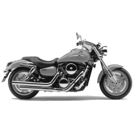
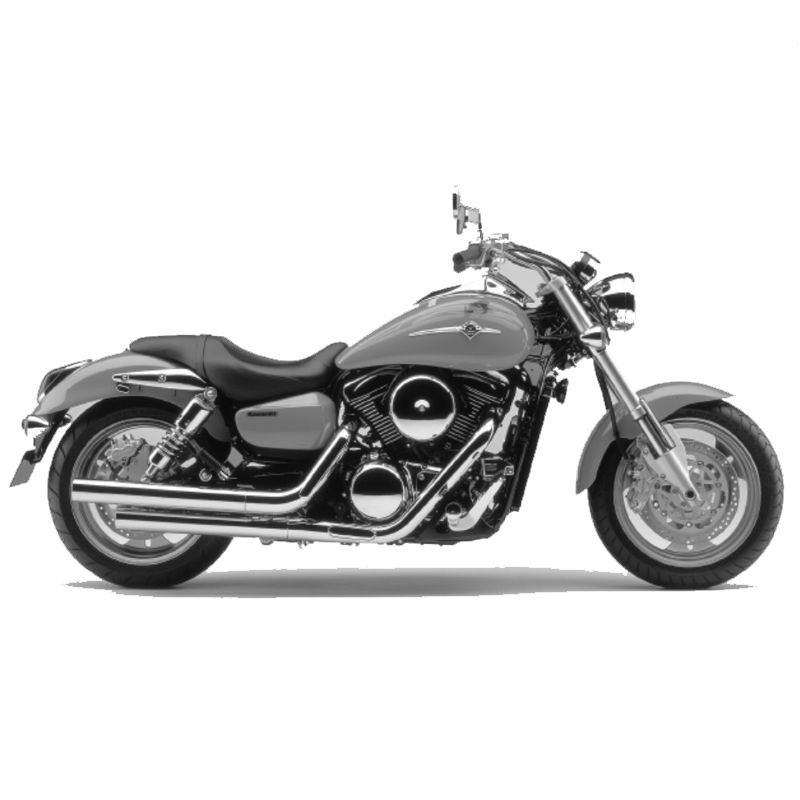
Kawasaki Vulcan 1600 Mean Streak VN1600 - Workshop & Wiring Manual
Technical documentation for Kawasaki Vulcan 1600 Mean Streak VN1600 combining service or workshop information with electrical diagram material specifically identified in the source index.
What is included: Workshop service information and explicitly listed regional circuit diagrams.
Document language information stated in the original listing: English and German.
Documented technical coverage
The source table of contents specifically lists Motorcycle maintenance manual; Crankshaft / gearbox; Brakes; Fuel system (DFI).
Diagram scope: The electrical material is limited to the sections specifically listed below; other schematics are not implied.
Original technical index
- SERVICE MANUAL
- Manual overview
- Motorcycle maintenance manual
- Preface
- General information
- - Preparations before starting maintenance work
- - Model identification
- - General technical data
- - Unit conversion table
- Regular maintenance
- - Periodic maintenance table
- - Tightening torque and thread lock
- - Technical specifications
- - Special tools
- - Measures for regular maintenance
- Fuel system (DFI)
- - exploded view
- - Location of the DFI parts
- - DFI system
- - Circuit diagram of the DFI system
- - Technical specifications
- - Special tools and sealants
- - Precautions for DFI maintenance
- - Troubleshooting the DFI system
- - Troubleshooting guide for the DFI system
- - self diagnosis
- - Throttle valve sensor (service code 11)
- - Intake air pressure sensor (service code 12)
- - Intake air temperature sensor (service code 13)
- - Water temperature sensor (service code 14)
- - Ambient pressure sensor (service code 15)
- - Crankshaft sensors (# 1, # 2: service code 21, 22)
- - Tip-over sensor (service code 31)
- - Injectors (# 1, # 2: service code 41, 42)
- - fuel pump (service code 45)
- - Ignition coils (# 1, # 2: service code 51, 52)
- - FI indicator LED
- - ECU
- - DFI power supply
- - ISC valves
- - fuel line
- - Throttle twistgrip and throttle cables
- - throttle body
- - air filter
- - fuel tank
- - tank vapor system
- Cooling system
- - Exploded views
- - Flow diagram of the cooling liquid
- - Technical specifications
- - Special tools and sealants
- - coolant
- - Water pump
- - cooler
- - thermostat
- - Hoses and lines
- Engine top
- - Exploded views
- - Technical specifications
- - Special tools and sealants
- - Exhaust gas cleaning system
- - Timing chain tensioner
- - rocker arm housing cover
- - rocker arm housing
- - camshafts
- - cylinder head
- - cylinder, piston
- - silencer
- coupling
- - exploded view
- - Technical specifications
- - Special tools and sealants
- - clutch fluid
- - clutch master cylinder
- - clutch slave cylinder
- - clutch
- Engine lubrication system
- - Engine oil lubrication scheme
- - exploded view
- - Technical specifications
- - Special tools and sealants
- - engine oil and oil filter
- - Oil pump and oil line
- - oil pressure
- Removal / installation of the engine
- - exploded view
- - Technical specifications
- - Removal / installation of the engine
- Crankshaft / gearbox
- - exploded view
- - Technical specifications
- - Special tools and sealants
- - crankcase
- - crankshaft and connecting rod
- - primary gear
- - Transmission
- - Ball bearings, needle bearings and oil seal
- Wheels / tires
- - exploded view
- - Technical specifications
- - Special tools
- - wheels (rims)
- - Tires
- - hub bearings (wheel bearings)
- Final drive
- - exploded view
- - Technical specifications
- - Special tools
- - Final drive housing and oil
- - cardan shaft
- - bevel gears of the axle output
- - Bearing and sealing ring
- Brakes
- - exploded view
- - Technical specifications
- - special tools
- - Brake lever, brake pedal
- - brake calipers
- - brake pads
- - master cylinder
- - brake discs
- - brake fluid
- - brake hoses
- suspension
- - exploded view
- - Technical specifications
- - Special tools
- - front fork
- - rear suspension strut (air cushioned)
- - swing arm
- steering
- - exploded view
- - Special tools
- - handlebars
- - steering
- - steering shaft
- - steering stem bearings
- frame
- - exploded view
- - Special tools
- - Seat
- - side cover
- - fenders
- - battery compartment
- - tool box
- - frame cross tube
- - side stand
- - rearview mirror
- - Frame
- Electrics
- - Position of the electrical components
- - exploded view
- - Circuit diagram (USA and Canada)
- - Circuit diagram (except USA, Canada and Australia)
- - wiring diagram (Australia)
- - Technical specifications
- - Special tools and sealants
- - Precautions for maintenance
- - wiring
- - battery
- - charging system
- - ignition system
- - starter
- - lighting system
- - Automatic turn signal switch-off
- - radiator fan
- - Oil pressure warning system
- - Instruments and displays
- - Water temperature warning system
- - Switches and sensors
- - fuse box
- - Backup
- attachment
- - Laying of cables, cables and hoses
- - Troubleshooting guide (except DFI)
- WERKSTATT-HANDBUCH
- Handbuchübersicht
- Motorrad Wartungshandbuch
- Vorwort
- Allgemeine Hinweise
- - Vorbereitungen vor Beginn der Wartungsarbeiten
- - Modellkennzeichnung
- - Allgemeine technische Daten
- - Einheitenumrechnungstabelle
- Regelmäßige Wartung
- - Tabelle zur regelmäßigen Wartung
- - Anzugsmoment und Gewindekleber
- - Technische Daten
- - Spezialwerkzeuge
- - Maßnahmen zur regelmäßigen Wartung
- Kraftstoffsystem (DFI)
- - Explosionszeichnung
- - Lage der DFI-Teile
- - DFI-System
- - Schaltplan des DFI-Systems
- - Technische Daten
- - Spezialwerkzeuge und Dichtmittel
- - Vorsichtsmaßnahmen bei DFI-Wartungsarbeiten
- - Fehlersuche im DFI-System
- - Fehlersuchanleitung für das DFI-System
- - Selbstdiagnose
- - Drosselklappensensor (Servicecode 11)
- - Ansaugluftdrucksensor (Servicecode 12)
- - Ansaugluft-Temperatursensor (Servicecode 13)
- - Wassertemperatursensor (Servicecode 14)
- - Umgebungsdrucksensor (Servicecode 15)
- - Kurbelwellensensoren (#1, #2: Servicecode 21, 22)
- - Umkippsensor (Servicecode 31)
- - Einspritzventile (#1, #2: Servicecode 41, 42)
- - Kraftstoffpumpe (Servicecode 45)
- - Zündspulen (#1, #2: Servicecode 51, 52)
- - FI-Anzeige-LED
- - ECU
- - DFI-Stromversorgung
- - ISC-Ventile
- - Kraftstoffleitung
- - Gasdrehgriff und Gaszüge
- - Drosselklappengehäuse
- - Luftfilter
- - Kraftstofftank
- - Tankdunstsystem
- Kühlsystem
- - Explosionszeichnungen
- - Flussdiagramm der Kühlflüssigkeit
- - Technische Daten
- - Spezialwerkzeuge und Dichtmittel
- - Kühlflüssigkeit
- - Wasserpumpe
- - Kühler
- - Thermostat
- - Schläuche und Leitungen
- Motoroberteil
- - Explosionszeichnungen
- - Technische Daten
- - Spezialwerkzeuge und Dichtmittel
- - Abgasreinigungssystem
- - Steuerkettenspanner
- - Kipphebelgehäusedeckel
- - Kipphebelgehäuse
- - Nockenwellen
- - Zylinderkopf
- - Zylinder, Kolben
- - Schalldämpfer
- Kupplung
- - Explosionszeichnung
- - Technische Daten
- - Spezialwerkzeuge und Dichtmittel
- - Kupplungsflüssigkeit
- - Kupplungsgeberzylinder
- - Kupplungsnehmerzylinder
- - Kupplung
- Motorschmiersystem
- - Schema der Motorölschmierung
- - Explosionszeichnung
- - Technische Daten
- - Spezialwerkzeuge und Dichtmittel
- - Motoröl und Ölfilter
- - Ölpumpe und Ölleitung
- - Öldruck
- Ausbau/Einbau des Motors
- - Explosionszeichnung
- - Technische Daten
- - Ausbau/Einbau des Motors
- Kurbelwelle/Getriebe
- - Explosionszeichnung
- - Technische Daten
- - Spezialwerkzeuge und Dichtmittel
- - Kurbelgehäuse
- - Kurbelwelle und Pleuel
- - Primärrad
- - Getriebe
- - Kugellager, Nadellager und Öldichtung
- Räder/Reifen
- - Explosionszeichnung
- - Technische Daten
- - Spezialwerkzeuge
- - Räder (Felgen)
- - Reifen
- - Nabenlager (Radlager)
- Achsantrieb
- - Explosionszeichnung
- - Technische Daten
- - Spezialwerkzeuge
- - Achsantriebsgehäuse und Öl
- - Kardanwelle
- - Kegelräder des Achsabtriebs
- - Lager und Dichtring
- Bremsen
- - Explosionszeichnung
- - Technische Daten
- - Spezialwerkzeug
- - Bremshebel, Bremspedal
- - Bremssättel
- - Bremsklötze
- - Hauptbremszylinder
- - Bremsscheiben
- - Bremsflüssigkeit
- - Bremschläuche
- Federung
- - Explosionszeichnung
- - Technische Daten
- - Spezialwerkzeuge
- - Vorderradgabel
- - Hinterrad-Federbein (Luftgedämpft)
- - Schwinge
- Lenkung
- - Explosionszeichnung
- - Spezialwerkzeuge
- - Lenker
- - Lenkung
- - Lenkschaft
- - Lenkschaftlager
- Rahmen
- - Explosionszeichnung
- - Spezialwerkzeuge
- - Sitz
- - Seitendeckel
- - Schutzbleche
- - Batteriefach
- - Werkzeugbox
- - Rahmenquerrohr
- - Seitenständer
- - Rückspiegel
- - Rahmen
- Elektrik
- - Position der elektrischen Bauteile
- - Explosionszeichnung
- - Schaltplan (USA und Kanada)
- - Schaltplan (außer USA, Kanada und Australien)
- - Schaltplan (Australien)
- - Technische Daten
- - Spezialwerkzeuge und Dichtmittel
- - Vorsichtsmaßnahmen bei der Wartung
- - Verkabelung
- - Batterie
- - Ladesystem
- - Zündsystem
- - Starter
- - Beleuchtungssystem
- - Blinker-Ausschaltautomatik
- - Kühlerlüfter
- - Öldruck-Warnsystem
- - Instrumente und Anzeigen
- - Wassertemperatur-Warnsystem
- - Schalter und Sensoren
- - Sicherungskasten
- - Sicherung
- Anhang
- - Verlegung von Seilzügen, Kabeln und Schläuchen
- - Anleitung zur Fehlersuche (außer DFI)