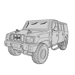
Daily Euro 4 Index
General Information & Vehicle Identification
- Vehicle identification plates, model configurations, and identification codes.
- General technical information and workshop procedures.
- Fluid specifications and replenishment information.
Engine Coverage — F1A & F1C
- Dedicated service and repair information for Iveco F1A and F1C diesel engines.
- Engine identification codes, technical specifications, and performance characteristics.
- Assembly clearances, tightening torques, and special workshop tools.
- Engine removal, installation, inspection, and overhaul procedures.
Engine Mechanical & Overhaul
- Cylinder block inspection, measurement, and repair.
- Crankshaft, main bearings, connecting rods, and pistons.
- Piston rings, gudgeon pins, crankshaft seals, and engine flywheel.
- Engine disassembly, mechanical inspection, and reassembly.
- Crankshaft end float, bearing clearances, and piston protrusion measurements.
Cylinder Head, Valves & Timing System
- Cylinder head removal, inspection, and installation.
- Valves, valve guides, seats, springs, rocker arms, and tappets.
- Camshaft inspection and timing system servicing.
- Timing belt replacement on applicable engines.
- Auxiliary drive belts, pulleys, and tensioning procedures.
Engine Lubrication & Cooling
- Engine oil pump, oil pressure control valves, and oil filters.
- Vacuum pump/oil pump assemblies and heat exchangers.
- Crankcase ventilation and oil vapour recirculation systems.
- Cooling system, water pump, thermostat, and electromagnetic fan coupling.
- Cooling and lubrication system maintenance and repair.
Turbocharging Systems
- Turbocharger operation, inspection, and service procedures.
- KKK K03-2074-CCB turbocharger.
- Garrett GT17 variable geometry turbocharger.
- Mitsubishi TD4 HL-13T-6 turbocharger.
- Garrett GT2260V variable geometry turbocharger.
- Turbocharger pressure control, solenoid valves, and actuator adjustment.
Diesel Fuel Injection — Common Rail
- Electronic high-pressure injection systems MS6.3 and EDC16.
- High-pressure fuel pumps, including CPH1 and CP3.2.
- Fuel rail, pressure regulators, fuel filters, and supply circuits.
- Electro-injector operation, testing, and replacement.
- Injection pressure and timing control.
- Fuel delivery, fuel recirculation, and hydraulic system components.
Electronic Engine Management & Diagnostics
- Bosch EDC16 engine management system.
- Engine control unit connections, sensors, and actuators.
- Engine speed, camshaft position, fuel pressure, and temperature sensors.
- Accelerator, clutch, and brake pedal position sensors.
- Electronic injection timing, idle control, and cylinder balancing.
- Glow plug control, engine starting, and operating strategies.
- Self-diagnosis, blink codes, and electronic troubleshooting.
Euro 4 Emission Control — EGR & DPF
- Euro 4 exhaust emission control systems.
- Exhaust Gas Recirculation (EGR) valve, control solenoid, and heat exchanger.
- Airflow meter and throttle valve assembly.
- Oxidation catalyst and exhaust system components.
- Diesel Particulate Filter (DPF) inspection and replacement.
- DPF regeneration system and forced regeneration procedures.
- Differential pressure (Delta-P) and exhaust temperature sensors.
- Service procedures following replacement of injection and exhaust after-treatment components.
Clutch & Hydraulic Controls
- Clutch inspection, removal, and installation.
- Clutch release bearing and hydraulic actuation system.
- Clutch pedal assembly and hydraulic control components.
- Automatic wear compensation clutch systems.
Manual Transmissions
- Service and overhaul procedures for:
- 5 S 300 transmission
- 6 S 400 O.D. transmission
- Gearbox removal, disassembly, inspection, and reassembly.
- Mainshaft, input shaft, gears, bearings, and synchronizers.
- Gear selection mechanisms, shift forks, and selector controls.
- Bearing clearances, transmission adjustments, and diagnostic procedures.
6 S 400 A O.D. Automated Transmission
- 6 S 400 A O.D. electronically controlled transmission.
- Transmission control unit, clutch actuator, and gear selection actuator.
- Gear selector, instrument display, and electronic management.
- Gear engagement, startup procedures, and fail-safe operation.
- Hill Holder function on applicable ESP 8 configurations.
- Gearbox removal, overhaul, and actuator replacement.
- MODUS, IT 2000, and E.A.Sy. diagnostic connections.
- Transmission calibration and electrical system diagnosis.
Power Take-Off (PTO)
- PTO system specifications and technical information.
- Power Take-Off electric actuator.
- PTO engagement and disengagement procedures.
Propeller Shafts & Driveline
- Propeller shaft inspection, maintenance, and repair.
- Driveshaft removal and installation.
- Driveline diagnostic procedures and technical specifications.
Rear Axles & Differentials
- Rear axle service and repair for NDA RS, NDA RG, 450511, and 450517/2 configurations.
- Wheel hubs, bearings, and axle components.
- Differential disassembly, inspection, and overhaul.
- Bevel pinion assemblies and differential housings.
- Differential locking mechanisms, servicing, and adjustment.
Front Axles & Wheel Alignment
- Front axle service for 5817, 5818, 5819, and 5823 configurations.
- Wheel hubs, steering knuckles, and axle components.
- Wheel alignment, toe-in, camber, and caster measurements.
- Steering angle, wheelbase, and rear axle alignment checks.
Front & Rear Mechanical Suspension
- Front suspension with leaf springs and torsion bars.
- Suspension arms, bushings, tie rods, and stabilizer bars.
- Front shock absorbers and torsion bar preload adjustment.
- Rear leaf springs, shock absorbers, and stabilizer components.
- Suspension service procedures for applicable 29L, 35S, 35C, 40C, 45C, 50C, 60C, and 65C variants.
Rear Air Suspension — WABCO ECAS
- WABCO ECAS electronically controlled pneumatic suspension.
- Air suspension components, pneumatic circuits, and electronic controls.
- Air springs, level sensors, and pneumatic supply units.
- Chassis height adjustment, self-levelling, and calibration.
- Electronic control unit programming and suspension troubleshooting.
Wheels & Tyres
- Wheel and tyre specifications.
- Tyre pressure inspection and adjustment.
- Static wheel balancing and fault diagnosis.
Steering & Hydraulic Power Steering
- TRW and ZF hydraulic power steering systems.
- Steering gear, hydraulic pump, and steering linkage.
- Power steering pressure testing and hydraulic system bleeding.
- Steering shaft, joints, and related component servicing.
Hydraulic Braking System
- Service, emergency, and parking brake systems.
- Front and rear disc brakes, calipers, and brake linings.
- Hydraulic brake pipes, hoses, and connections.
- Brake fluid circuit inspection and bleeding.
- Vacuum brake assistance and load sensing valves.
- Parking brake inspection, overhaul, and adjustment.
ABS 8, ESP 8 & Stability Control
- ABS 8 anti-lock braking system.
- ESP 8 electronic stability program.
- Electronic Brakeforce Distribution (EBD).
- Anti-Slip Regulation (ASR) and engine braking torque control.
- Hill Holder Control (HHC) and Hydraulic Brake Assist (HBA).
- Electrohydraulic modulators and electronic control units.
- Wheel speed, steering angle, yaw, and acceleration sensors.
- ABS/ESP diagnostics, programming, and calibration.
Cab Heating, Ventilation & Air Conditioning
- Cab heating, ventilation, and air conditioning systems.
- Magneti Marelli and Denso climate control equipment.
- Compressor, condenser, evaporator, expansion valve, and receiver/drier.
- Climate control electronic unit, pressure switches, and temperature sensors.
- R134a refrigerant recovery, evacuation, charging, and pressure testing.
- Air conditioning fault diagnosis and service procedures.
Scheduled Maintenance
- Maintenance schedules for F1A and F1C engine vehicles.
- Periodic inspection and service operations.
- Additional maintenance interventions and maintenance point diagrams.
Electrical Power Distribution & Components
- Battery, alternator, and starter motor systems.
- Electrical power distribution, positive and ground networks.
- Instrument panel and engine compartment fuse/relay units.
- CPL 75002 and CVM 75001 electrical distribution units.
- Junction connectors, electrical harnesses, and grounding points.
- Instrument cluster, dashboard controls, and steering column switches.
Body Computer & CAN Communication
- Body Computer system and electronic control functions.
- B-CAN and C-CAN communication networks.
- Junction connectors and control unit pin assignments.
- Vehicle electrical communication and diagnostic connections.
Engine Electronic Wiring & Control Units
- EDC16 injection control for F1A and F1C engines.
- ECU connector pinouts and wiring connections.
- Engine sensors, injectors, fuel pressure, and temperature circuits.
- Preheating, cooling fan, and electronic actuator controls.
- EGR and DPF-related electronic components.
- Engine and cab wiring harness connections.
Airbags, Pretensioners & Immobilizer
- Driver and passenger airbag systems.
- Curtain airbags and seat belt pretensioners.
- Airbag control unit connections and component replacement.
- Airbag safety procedures and passenger airbag deactivation.
- Immobilizer, vehicle keys, antenna, and Body Computer integration.
Electrical Wiring Diagrams
Dedicated electrical circuit diagrams covering:
- Power distribution, fuses, relays, and grounding.
- Cab interior electrical components.
- Electric windows and electrically operated mirrors.
- Exterior lighting and vehicle warning systems.
- Bosch EDC16 electronic diesel injection.
- ABS 8, ESP 8, and ASR electronic braking systems.
- 6 S 400 A O.D. automated transmission.
- WABCO ECAS air suspension.
- Cruise control and climate control.
- Power Take-Off and additional heating.
- Differential locking and heated glass.
- Telma retarder electrical circuits.
- Airbag and restraint systems.
- Camera equipment and auxiliary electrical functions.
- CAN communication networks.
Electrical Connectors & Diagnostic Reference
- Control unit connector identification and pinout information.
- Fuse and relay location diagrams.
- Electronic transmission, ABS/ESP, and engine ECU connections.
- EOBD diagnostic connector information.
- Electrical circuit symbols, technical codes, and wiring reference tables.
Workshop Technical Data
- Engine, clutch, gearbox, axle, suspension, steering, and brake specifications.
- Assembly measurements, mechanical clearances, and tightening torques.
- Special tools and diagnostic equipment.
- Hydraulic, pneumatic, and electrical circuit diagrams.
- Electronic diagnostic procedures, component programming, and system calibration.
The Reality of Commercial Fleet Repairs
High-pressure fuel systems require precise handling during any repair, especially on the Daily Euro 4's common rail architecture. A common issue technicians encounter on the 2.3L F1A and 3.0L F1C engines revolves around the D.P.F. (Diesel Particulate Filter) catalyst.
Often, an OBD2 sensor diagnostics scan points directly to a failing Delta-P (Differential Pressure) sensor. Mechanics will routinely swap the electrical sensor, only to have the van return to the bay three days later. One frequent diagnostic mistake is overlooking the mechanical side of the equation—specifically, microscopic cracks in the metal pressure pipes leading to the sensor, or extreme soot loading physically blocking the exhaust gas flow. This technical document provides the step-by-step procedures for testing the Delta-P sensor voltage, alongside the mechanical instructions for inspecting the D.P.F. and performing a forced regeneration, ensuring you fix the actual root cause.
F1A & F1C Powertrain Integration
Modern commercial vans blur the line between mechanical iron and digital logic. The Bosch EDC 16 electronic injection system dictates every movement of the engine based on physical feedback.
If an F1C engine has slight mechanical wear on the camshaft timing gear, the resulting vibration can slightly skew the air gap on the camshaft timing sensor. The EDC 16 interprets this erratic signal as a fueling error, altering the injector pulse width and causing a rough idle. By utilizing these OEM service instructions, you gain access to the correct tightening sequences for the timing drive, as well as the exact electrical testing values for the rpm/timing sensors.
Drivetrain Stress & ESP 8 Network
Hauling heavy loads severely punishes the drivetrain components. When repairing the rear axles—whether it is the NDA RS, NDA RG, or the heavier 450517/2—setting the mechanical clearances on the differential is critical.
In many real-world repair cases, improper torque applied to the bevel pinion during a differential rebuild creates a high-frequency driveline vibration. What starts as a mechanical humming quickly becomes an electrical headache. The intense vibration travels through the rear axle casing and disrupts the signal from the ABS 8 / ESP 8 wheel speed sensors. The central unit detects a sudden discrepancy in wheel speed and abruptly deactivates the Electronic Stability Program. This resource gives you both the factory torque specifications to perfectly rebuild the axle and the wiring circuits to verify the integrity of the ESP sensor harnesses.
Cab Electronics & Active Suspension
Tracing a Daily Euro 4 parasitic draw diagnosis is notoriously difficult due to the multiplexed CAN lines (B and C). This guide maps out all 16 circuit cards, pinpointing every junction connector (L, M, R, H) leading back to the Body Computer. Furthermore, for models equipped with the Wabco ECAS (Electronically Controlled Air Suspension), you receive the complete mechanical replacement procedures for the air springs and load sensing valves, integrated directly with the electronic calibration steps for the ride height sensors.
Why Accurate Factory Data Matters
Attempting to service the Garrett GT 2256 T Variable Geometry Turbocharger (VGT) without knowing the required vacuum actuator parameters often results in destroying the turbine. This mechanical and electrical repair PDF gives you the absolute truth: from the exact millimeter stroke required for the VGT actuator rod to the refrigerant capacity for the Marelli or Denso cab air-conditioning units.
- Searchable Text: Instantly jump to the F1C engine tightening torques or the 6S 300 transmission bearing end-float specs.
- High-Resolution Schematics: Zoom in on intricate engine harness layouts and CAN-bus communication lines without blurring.
- Cross-Device Compatibility: Open the PDF on a shop tough-book, an iPad under the hood, or print specific pages for dirty bench work.
Instant Shop Floor Guarantee
A truck taking up space on your lift is burning money. We ensure you get your diagnostic data immediately.
- Payment Methods: Checkout securely using your Credit Card, PayPal, Google Pay, or Apple Pay.
- Instant Delivery: A download service manual PDF link is fired directly to your email and saved permanently in your customer account.
- Flexible Access: Your secure link remains active for 10 days or up to 10 unique downloads.
- Failsafe Backup: If your shop Wi-Fi drops out during the large file transfer, reach out to us for a direct Dropbox backup link.
- Need help saving the file? Watch our fast visual tutorial right here: https://servicemanuals.info/How-to-Download.mp4
Access the full PDF guide now and eliminate guesswork in your repairs.
Field Troubleshooting FAQ
How do I bleed the ABS/ESP hydraulic circuit after replacing a brake caliper?
The braking section explicitly details the electronic and manual bleeding sequence for the ESP 8 electro-hydraulic modulator. It walks you through opening the specific ABS valves via diagnostic commands while mechanically flushing the lines to prevent trapped air from causing a spongy pedal.
Will this technical document help me wire a PTO onto an AGile transmission?
Yes. The manual covers both ZF and Hydrocar Power Take-Off (PTO) systems. It provides the specific mechanical assembly standards for the gearbox side and the electrical actuator wiring required to safely integrate the PTO control switch into the vehicle's multiplex network.
What is the correct procedure for testing the VGT solenoid valve on the 8140.43S engine?
During troubleshooting, you must isolate the vacuum supply from the electrical command. This resource outlines the exact PWM (Pulse Width Modulation) voltage signals the EDC MS6.3 module should be sending, as well as the mechanical vacuum gauge tests required to ensure the actuator rod is physically moving the turbo vanes without binding.
Are the wiring diagrams separated for the different interior configurations?
Absolutely. The massive 400+ page electrical library features dedicated schematic diagrams (SD) for panel vans, chassis cabs, and multi-passenger variants. It covers everything from standard cab lighting to the complex rotating sliding door circuits and roof ventilation systems.